
General assembly tips/instructions for AMORE
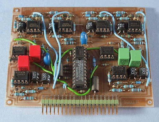
An AMORE board (the VCBPF).
If you are going to use the AMORE board as a module for a modular synth, you need to make a front panel for it. As the inputs on the amore board are summing nodes, you need to add at least a resistor between your signal source and the board input. I recommend the following circuit, which you can build on a Veroboard and mount behind the front panel of the module:
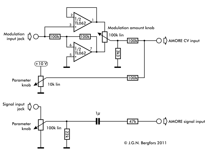
If you have built the AMORE exerciser, you don't need to complete the front panel to be able to build/test the circuit board though.
The AMORE standard connector
|
Connector pin |
signal |
|
1 |
1 oct/V |
|
2 |
in 1 |
|
3 |
CV 1 |
|
4 |
CV 2 |
|
5 |
CV 3 |
|
6 |
-15 V |
|
7 |
out 1 |
|
8 |
-1 V |
|
9 |
gnd |
|
10 |
key |
|
11 |
bypass 1 |
|
12 |
bypass 2 |
|
13 |
out 2 |
|
14 |
+15 V |
|
15 |
+10 V |
|
16 |
undefined |
|
17 |
in 2 |
|
18 |
CV 4 |
|
19 |
CV 5 |
|
20 |
CV 6 |
Populating the board
The most convenient way to populate the circuit boards is to solder the parts in the order of height. You start with the lowest parts, which are the short wire links made of unisolated wire (resistor clippings). Then you commence in the following order:
Miniature resistors
Diodes
Normal resistors
IC sockets
The edge connector
Ceramic capacitors
Trim potentionmeters
Polyester/polypropylene capacitors
Electrolytic capacitors
Vertically mounted resistors
Transistors
Isolated wire links
Testing the board
Insert the board in
the exerciser and turn the power on and then quickly off again. Note
if all three LEDs for the supply voltages did light up. If not, there
is a short circuit on the board that you need to fix.
Next, turn
power on and quickly off again. Note how quickly the LEDs fade out.
If they go out much quicker than with no board in the exerciser,
there is something that draws excessive power. This can be caused by
a solder bridge (short) or improperly mounted parts. Check for
errors.
Turn on power again an let it be on a little longer. Feel
with your hand if some parts seem to get hot. In that case, turn
power off immediately and check for errors.
If nothing gets hot,
you can let the power stay on. Now is the time to measure the supply
voltage at every IC socket. The supply pins are clearly marked on the
component placement plan, so this should be straightforward. If the
supply voltage is missing somewhere, you might have forgotten a wire
link or there might be a bad solder joint or a defect in the circuit
board.
When you have supply voltage everywhere, you can mount the
ICs. Only mount the ICs for one functional block at a time (VCO core,
waveshaper sections, output selector etc). When you have one block
functioning, you mount the ICs for the next and check the function
etc. until all functions are operable.
Now It's time to trim the
various functions, if the board is equipped with trimmers (most are).