
BC550C VCA 2

This is the same circuit as the BC550C VCA 1,
except that some resistors have been changed. As the original
circuit exceeded 1% distortion at 10 V p-p input signal, the
input divider resistors were changed to reduce the signal
further. Instead the control current was increased, as this
improved performance slightly.
This circuit has the lowest signal bleedthrough at 10 kHz, but
apart from this the performance isn't particularly good. As with
the BC550C VCA 1, CV bleedthrough and temperature sensitivity are
problem areas.
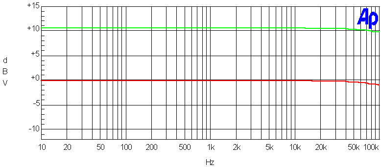
Noise & signal attenuation
Red = signal bleedthtrough at 0V CV. Blue = 10V CV, no signal. Green = 0V CV, no signal.

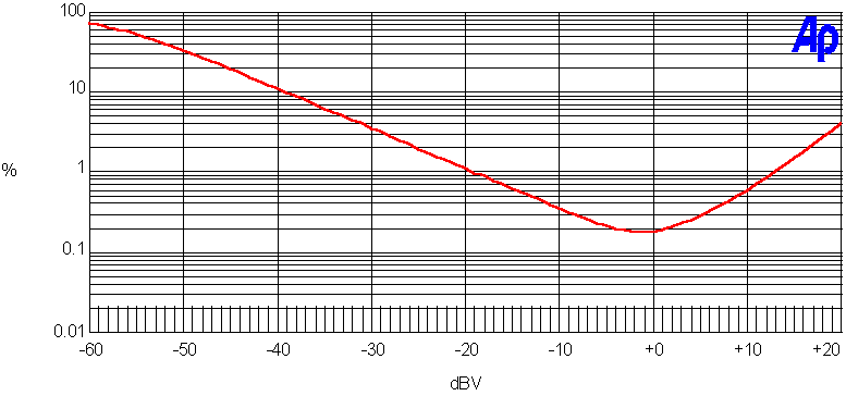
Distortion (THD+N) vs. input level
Frequency response
Test results
| Dynamic range | 10 V CV, no signal | 80 dBr A |
| 0 V CV, no signal | 97 dBr A | |
| 0 V CV, 1kHz 10 V p-p in | 95 dBr A | |
| 0 V CV, 2 kHz 10 V p-pin | 94 dBr A | |
| 0 V CV, 10 kHz 10 V p-pin | 87 dBr A | |
| Headroom (over 10V p-p) | 2 dB | |
| CV bleedthrough | with careful trimming | 220 mV |
Summary
In contrast to what some people seems to think, a simple discrete circuit like this has no advantages over an OTA-based one.
+
• Low signal bleedthrough
–
• High CV bleedthrough
• Temperature sensitive
• Needs matched transistors