
LM13600 VCA 2

This circuit is identical to LM13600 VCA 1, with the exception of the output stage. Here, the load resistor is in the feedback loop of an inverting amplifier, instead of connected to ground. The effect this has on performance turned out to be neglible. Signal bledthrough seems to be very slightly better, which makes this circuit to the overall winner.
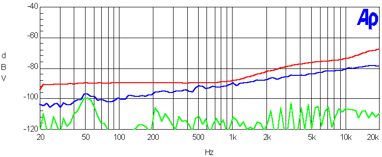
Noise & signal attenuation
Red = signal bleedthtrough at 0V CV. Blue = 10V CV, no signal. Green = 0V CV, no signal.
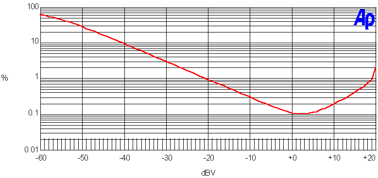
Distortion (THD+N) vs. input level
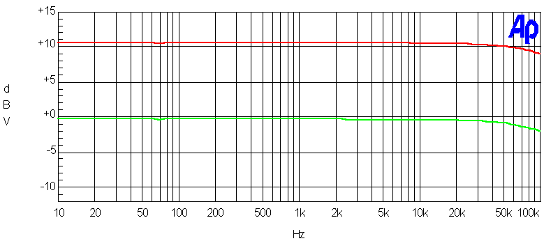
Frequency response
Test results
| Dynamic range | 10 V CV, no signal | 82 dBr A |
| 0 V CV, no signal | 109 dBr A | |
| 0 V CV, 1kHz 10 V p-p in | 98 dBr A | |
| 0 V CV, 2 kHz 10 V p-pin | 93 dBr A | |
| 0 V CV, 10 kHz 10 V p-pin | 85 dBr A | |
| Headroom (over 10V p-p) | 8 dB | |
| CV bleedthrough | after careful trimming | 20 mV |
Summary
A good, low cost VCA
+
• Low signal bleedthrough
• Low distortion
• High headroom
–
• Rather low input inpedance