
LM13600 VCA 3

The same circuit as LM13600 VCA 2, except that
the chip is driven a bit harder. The Iabcat 10V CV is
increased to 1 mA and the input signal is increased slightly. To
maintain unity gain, the load resistor is reduced accordingly.
The effect of these changes is that the signal bleedthrough is
somewhat reduced. There is very little improvement in signal to
noise ratio.
Unfortunately the control voltage bleedthrough goes up when the
chip is driven harder. This circuit has the lowest signal
bleedthrough of the lot, but with higher CV bleedthrough it is
probably not preferrable to LM13600 VCA 2.
Noise & signal attenuation
Red = signal bleedthtrough at 0V CV. Blue = 10V CV, no signal. Green = 0V CV, no signal.

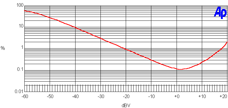
Distortion (THD+N) vs. input level
Frequency response

Test results
| Dynamic range | 10 V CV, no signal | 83 dBr A |
| 0 V CV, no signal | 110 dBr A | |
| 0 V CV, 1kHz 10 V p-p in | 105 dBr A | |
| 0 V CV, 2 kHz 10 V p-pin | 101 dBr A | |
| 0 V CV, 10 kHz 10 V p-pin | 86 dBr A | |
| Headroom (over 10V p-p) | 7 dB | |
| CV bleedthrough | after careful trimming | 40 mV |
Summary
Driving the chip this hard probably has more disadvantages than advantages.
+
• Very low signal bleedthrough
• Low noise
• High headroom
–
• Fairly low input inpedance
• CV bleedthrough slightly high