
Super Syncussion
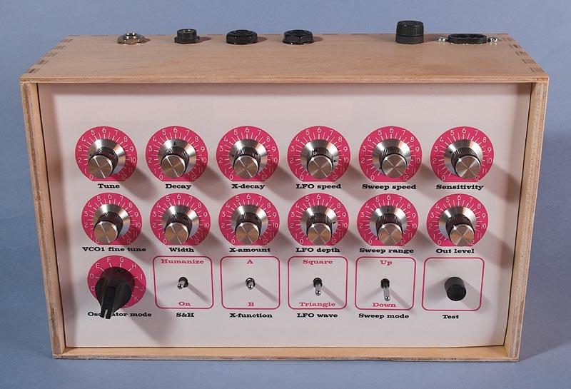
The Super Syncussion is housed in a wooden box from IKEA.
The Bergfotron
Super Syncussion is a complete synthesizer on a circuit board. It's
essentially a clone of the Pearl Syncussion SY-1, but has been
enhanced with some functions that add an extra dimension to the
sound.
The Syncussion is an analog synthesizer that was designed
to make percussion-type sounds. It came with drum pads to play the
sounds from and had two identical channels with individual controls,
so you could play two different sounds at once.
The Syncussion
synth voice consists of two VCOs, one lowpass VCF, one VCA with
envelope generator (only decay control), one envelope generator for
sweep effects, a noise generator, an LFO, a sample & hold and a
trig section for interfacing with the drum pads.
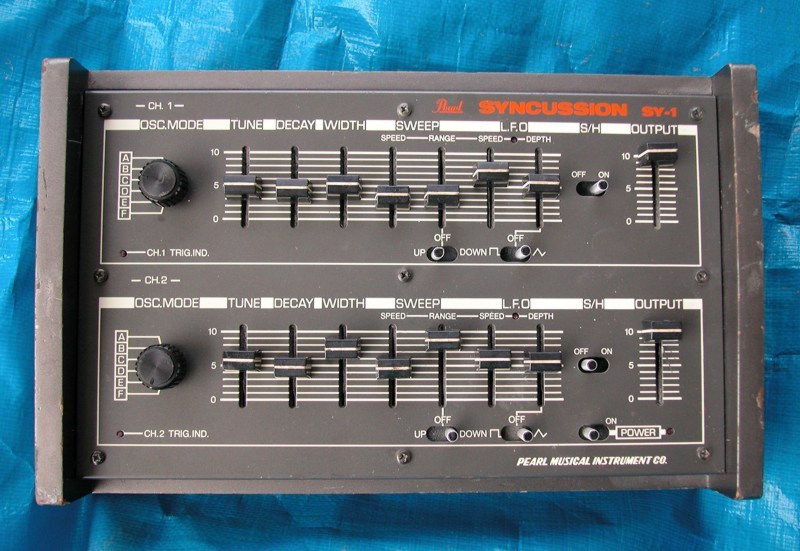
The
original Pearl Syncussion SY-1
The
Bergfotron Super Syncussion has all the features of the original
Syncussion and adds to that an extra VCA with it's dedicated envelope
generator and a ring modulator. Some extra knobs and switches are
added to control the extra functions and to increase the sonic power
of the unit. The Super Syncussion board has only one channel though,
so if you want to mimic the original Pearl unit, you need two boards.
Note that the Super Syncussion can do exactly the same sound as the
original SY-1, if you refrain from using the extra functions. I added
a knob for fine-tuning the VCO 1. On the original Syncussion, you
can't adjust the relative tuning between the two oscillators, unless
you open up the box and adjust a trimmer. That's probably the biggest
limitation of that unit.
The idea was to add an extra dimension to
the sound. This is where the extra VCA and envelope generator is
used. You can add an extra component to the sound and have control
over amount and decay time. So you could for instance add some detail
to the attack of the sound and let the normal sound take over during
the decay.
The original SY-1 offers white noise, which sounds
rather soft. I wanted noise with more punch, to mimic cymbals and
similar sounds. For this, I added a ring modulator. This is a very
simple unit, consisting of XOR gates. By ring-modulating the two VCOs
together, you can get clangy sounds, like cowbells. To get a more
dense spectrum, required by cymbal sounds, I added a fixed oscillator
that gets ring-modulated with the output from the first ring
modulator. This oscillator is constructed around the two unused gates
in one 4070 package. These two different outputs from the ring
modulator are available in different combinations in some of the
oscillator modes.
Since the ”oscillator modes”
controls the patching of the synth, I added six more modes, to make
use of the extra features. For each of the oscillator modes I also
added a selection of two extra functions. This is where the extra VCA
and envelope generator comes in. What component the extra functions
bring in, is different for each oscillator mode. Note that the six
oscillator modes from the original SY-1 have extra functions too. You
will have to set the extra function amount knob to zero, to mimic the
sound of the original SY-1.
Here
is an overview of the oscillator modes with standard and extra
functions. Note that the standard functions of mode A – F are
exactly the same as on an original Pearl Syncussion SY-1.
Oscillator
mode
Basic
function Extra
function
A
VCO
1 only X
B
VCO
1 modulates VCO 2 frequency, the latter routed to the VCF Y
C
Both
VCO to the filter but VCO1 at reduced level. Y
D
EG
1 modulates VCO1, EG2 modulates VCO2. Both VCO to the filter X
E
VCO
1 modulates VCO 2 which has a sawtooth wave. VCO 2 to VCF X
F
Noise
to VCF, no oscillators Z
G
VCO
2 to VCF, EG 2 modulates VCO 2, VCO 1 modulates VCF Y
H
VCO
2 with sawtooth to VCF Z
I
VCO
2 with triangle to VCF Z
J
Ringmod
1 to VCF Y
K
EG
2 modulates VCO 2, Ringmod 1 to VCF X
L
LPF
noise modulates VCO 2, which is routed to the VCF Z
Extra
functions
A
B
X
VCF
feedback
LPF
noise to VCA 1
Y
Noise
to VCF
Ringmod
2 to VCF
Z
VCO
1 modulates VCF cutoff Ringmod
2 to VCA1
Note:
You
can select extra function A or B with a toggle switch.
The
extra function has a dedicated VCA and EG, so you can control the
amount and decay for the extra function with two knobs.
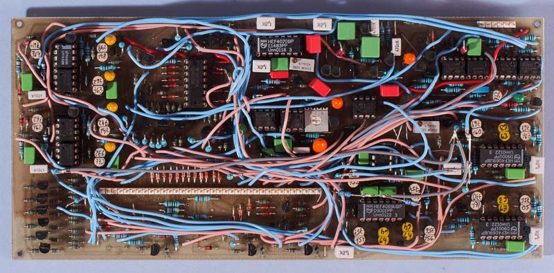
The
Super Syncussion board contains all electronics and interfaces with
the front panel through a large connector. This is the prototype
board. The final version of the board has a lot of errors and
omissions corrected.
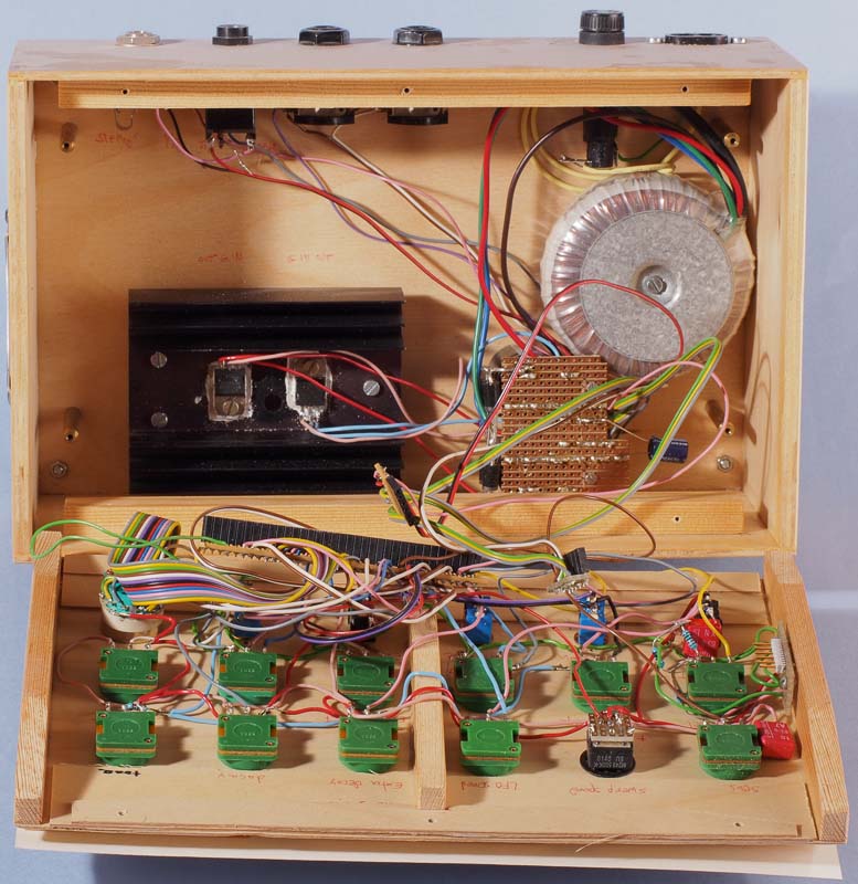
The
box contains a simple power supply that delivers -8 and +8 volts. In
this picture the main circuit board is removed.
The
circuit board measures 100 x 220 mm and is packed with electronics.
Due to the board containing an entire synth, with on-board patching,
there are a large number of wires to connect the different modules.
The rotary switch labelled “oscillator mode” is really a
sort of patch selector, since it controls how the modules are patched
together. This makes it very quick and easy to change patches, but it
requires a lot of electronics and wiring ”behind the scenes”.
Bill of materials
You
should have access to the parts in the general
bill of materials.
In addition, you need the following parts:
CD4050
hex buffer (1)
CD4069 hex inverter (3)
CD4070 quad EXOR gate
(1)
MC4558 dual low performance op-amp (11)
Noisy NPN
transistor for the noise generator. (I used a 2SC828, but note that
the board layout doesn't match the pinout on that transistor)
7808
+8 V voltage regulator (1)
7908 -8 V voltage regulator (1)
Matching
The transistors that are paired on the circuit board should be matched. The original Pearl Syncussion used dual transistors – 2SA798 for the PNP pairs and 2SC1583 for the NPN pairs. If you're lucky enough to have access to these, you don't need to match transistors. For hand-matching single transistors, you can use the Bergfotron transistor matcher.
Trimming
There are only two trimmers in this unit.
Noise
level
This
is for setting the gain of the white noise generator. You can adjust
it to your liking. I don't know how they did the adjustment at the
Pearl factory.
Fixed
oscillator frequency
This
trimmer sets the frequency of the fixed oscillator that is used only
by the ring modulator waveform Ring2. Listen to the sound and adjust
the trimmer until the Ring2 sounds as much as possible like a cymbal
or produces a sound that you like. You can replace this trimmer with
a front panel mounted potentiometer if you like to have more control.
There are two unused pins on the front panel connector that you can
use for this.
Skill level required: HIGH
For this module you need to match transistor pairs or obtain matched dual transistors. Otherwise there are no particular difficulties, but there is a large number of parts on the board and you need to make a lot of wire connections between different parts of the board.
Schematics for the original Syncussion SY-1
Schematics for the original Syncussion SY-1 power supply
Schematics for the changed oscillator mode logic
Schematics for the extra functions
Schematics for the ring modulator
Schematics for the front panel
Schematics for a modern power supply
|
Connector pin |
signal |
explanation |
|
1 |
osc 3 pot |
optional (see text) |
|
2 |
osc 3 pot |
optional (see text) |
|
3 |
VCA 1 out |
to output level pot |
|
4 |
tune CV |
from tune pot, LFO depth pot, sweep range pot, S&H switch |
|
5 |
LFO speed pot |
from wiper |
|
6 |
LFO square |
to toggle switch |
|
7 |
LFO triangle |
to toggle switch |
|
8 |
LFO LED |
- |
|
9 |
S&H out |
to S&H/humanize toggle switch |
|
10 |
up |
to up/down toggle switch |
|
11 |
down |
to up/down toggle switch |
|
12 |
sweep speed pot |
from wiper |
|
13 |
sensitivity pot |
from wiper |
|
14 |
EG 2 out |
to width pot |
|
15 |
width pot |
from wiper |
|
16 |
decay pot |
from wiper |
|
17 |
VCO 1 fine pot |
from wiper |
|
18 |
mode L |
to oscillator mode switch |
|
19 |
mode K |
to oscillator mode switch |
|
20 |
mode J |
to oscillator mode switch |
|
21 |
mode I |
to oscillator mode switch |
|
22 |
mode H |
to oscillator mode switch |
|
23 |
mode G |
to oscillator mode switch |
|
24 |
mode F |
to oscillator mode switch |
|
25 |
mode E |
to oscillator mode switch |
|
26 |
mode D |
to oscillator mode switch |
|
27 |
mode C |
to oscillator mode switch |
|
28 |
mode B |
to oscillator mode switch |
|
29 |
mode A |
to oscillator mode switch |
|
30 |
extra func. A/B |
from extra function toggle switch |
|
31 |
VCA 2 out |
to extra function level pot |
|
32 |
extra func. level pot |
from wiper |
|
33 |
extra func. decay pot |
from wiper |
|
34 |
trig LED |
- |
|
35 |
humanize |
from S&H/humanize toggle switch |
|
36 |
spare |
not used |