
ARP 4014 ring modulator clone (AMORE)
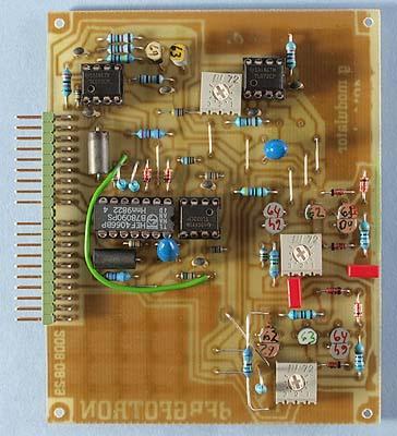
The prototype version of the board.
A ring modulator
multiplies the voltages on two inputs and sends the result to the
output. Ring modulators have been done in several different ways over
the years. The ARP 2600 is renown for its clean sounding ring
modulator. This was probably due to its somewhat unconventional
circuit design, with the positive and negative parts of the signal
split between two two-quadrant multipliers. It has a pre-distortion
circuit to minimize the deadband between the two multipliers but it
still works a little bit like it has a built-in noise gate. Both the
the ARP 2500 and the 2600 used the 4014 ring modulator module. This
is a clone of that circuit.
This module is based on discrete
transistors for the multiplication effect. These need to be
carefully matched and kept at the same temperature. You should pot
the transistor pairs in some isolating material, like a blob of
Araldite or something similar. This is not yet done on the prototype
board in the picture above. I used ordinary BC550C and BC560C
transistors, which works very well if you match them carefully and
couple them thermally. The only other difference from a vintage ARP
unit is the modern op-amps used. The ARP 4014 used LM301 op-amps
which had external frequency compensation, whereas modern op-amps
have internal frquency compensation. So there are a couple of
capacitors missing in my version. I suppose the different op-amps
could make a difference in the sound, but probably not much.
There
are no voltage controlled parameters on this module. There are two
voltage controlled switch functions though. One mutes the output and
the other sends a mix of the inputs to the output instead of the ring
modulator output.
Note that this ring modulator is DC-coupled, so
you can use it to process control voltages as well as audio signals.
When you integrate this board in a module, you should add external
DC-blocking capacitors that can be bypassed with a switch, just like
it is done in the AMORE exerciser (and in the ARP 2600). Note that
you can even mix audio signals and low frequency signals because the
latter makes a difference in the multiplied output. A ring modulator
is very versatile and more useful than many people realize. If you
for instance multiply an audio signal with an LFO signal, it works
like a VCA and creates a tremolo effect. But with the difference that
the modulation can go through zero.
Bill of materials
You should have access
to the parts in the general bill of
materials.
In addition, you need the following less common
parts:
There are no special parts needed.
Trimming
There are three trimmers on this board:
Pos. null, Neg.
null
With full signal on the Y input and no signal on the X
input, these should be adjusted for at little signal as possible at
the output. Let the module be powered up for at least ten minutes
before you do the adjustment.
Gain trim
Adjust
this so that the output signal will be 10 volts when both inputs have
5 volt signals.
Skill level required: MEDIUM
The only real difficulty with this module is matching the transistors. You could use matched pairs like MAT01 and MAT03 if you want to make things simple. This comes with a price though – the MAT pairs are very expensive.
|
Connector pin |
signal |
on this module |
|
1 |
1 oct/V |
not used |
|
2 |
in 1 |
Y input |
|
3 |
CV 1 |
not used |
|
4 |
CV 2 |
not used |
|
5 |
CV 3 |
not used |
|
6 |
-15 V |
-15 V |
|
7 |
out 1 |
output |
|
8 |
-1 V |
-1 V |
|
9 |
gnd |
gnd |
|
10 |
key |
- |
|
11 |
switch 1 |
mix |
|
12 |
switch 2 |
mute |
|
13 |
out 2 |
not used |
|
14 |
+15 V |
+15 V |
|
15 |
+10 V |
not used |
|
16 |
aux output |
not used |
|
17 |
in 2 |
X input |
|
18 |
CV 4 |
not used |
|
19 |
CV 5 |
not used |
|
20 |
CV 6 |
not used |