
Dual voltage controlled amplifier (AMORE)
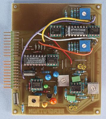
The prototype version of the board. There are a few differences compared to the final board.
This simple module consists of two logarithmic VCAs and – as an additional bonus – a noise generator. The latter is a clone of the Roland TR-808 and generates white noise. It has a separate output but can be routed through one of the VCAs if you want to voltage control the noise amplitude. If you don't require the noise generator, you can just omit the parts for it.
The VCAs are based on
the LM13600 (or LM13700) and produce a clean sound, with a fairly low
noise level. The VCAs are DC-coupled so you can use them to process
control voltages in addition to audio signals.
The LM13600 OTA
is rather difficult to find nowadays but the LM13700 seems to be
still in production. I have tested the circuit with both OTA types
and it seems the LM13700 has slightly lower gain but otherwise works
exactly like the LM13600. So if you use the LM13700, you might want
to increase the feedback resistor on the output op-amp from 47k to
56k or 62k so you get unity gain when CV is either 0 or 10V.
The
noise generator uses a 2SC828 transistor as a noise source. This is
the transistor originally used in the TR-808. Other noisy NPN
transistors should work too. You can try different transistors and
select the noisiest one. If you route the noise output to one of the
VCA inputs, you should add a 100 kohm resistor inbetween.
Bill of materials
You should have access
to the parts in the general bill of
materials.
In addition, you need the following less common
parts:
2SC828 Noisy NPN transistor
Trimming
There are two trimmers for each VCA and one for the noise generator:
VCA offset
Adjust
the trimmers so there is minimal change in the DC voltage at the
output when you sweep the CV with no input signal.
CV offset
Set
the CV knob to max, connect a VCO to the VCA input and adjust this
trimmer until the output signal stops to increase (or starts to
decrease, depending on which way you turn).
Noise level
The
noise generator has a trimmer fr setting noise amplitude. It's a bit
difficult to set this with an oscilloscope. It's better to listen to
the noise in speakers and adjust it until the noise is approximately
as loud as the waveforms from a VCO.
Skill level required: LOW
This module needs no matching of components and uses no hard to find parts.
|
Connector pin |
signal |
on this module |
|
1 |
1 oct/V |
not used |
|
2 |
in 1 |
input to VCA 1 |
|
3 |
CV 1 |
not used |
|
4 |
CV 2 |
not used |
|
5 |
CV 3 |
amplitude CV 1 |
|
6 |
-15 V |
-15 V |
|
7 |
out 1 |
output from VCA 1 |
|
8 |
-1 V |
-1 V |
|
9 |
gnd |
gnd |
|
10 |
key |
- |
|
11 |
switch 1 |
bypass VCA 1 |
|
12 |
switch 2 |
bypass VCA 2 |
|
13 |
out 2 |
output from VCA 2 |
|
14 |
+15 V |
+15 V |
|
15 |
+10 V |
not used |
|
16 |
aux output |
noise output |
|
17 |
in 2 |
input to VCA 2 |
|
18 |
CV 4 |
not used |
|
19 |
CV 5 |
not used |
|
20 |
CV 6 |
amplitude CV 1 |