
SSM 2040 style VCF + discrete VCA (AMORE)
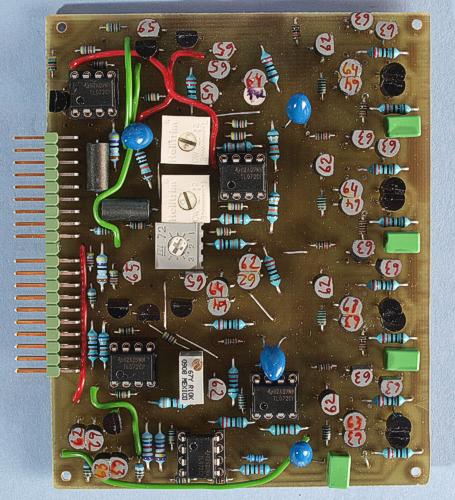
The prototype version of the board. There are a few differences compared to the final board.
This AMORE module combines a VCF based on a discrete clone of the SSM 2040 filter IC with a two stage discrete VCA on one half size board. Both of these circuits were developed by René Schmitz, and you can find the schematics on his web site (links below). This module is fully plug compatible with the Minimoog clone VCF + VCA.
The
filter is basically a discrete clone of the SSM 2040 IC, which were
used in some commercial synths back in the 80's. This IC has been out
of production for many years and is now very hard to find. Therefore,
both Jürgen Haible and René
Schmitz have done discrete clones of the IC. Their versions are
naturally very similar but not identical. I chose René
Scmitz version. The filter sounds a bit different than the
classic Moog ladder filter and I notice that it doesn't track 1 V/oct
very well above circa 2 kHz. Neither Jürgen Haible nor René
Schmitz have a trimmer for adjusting the tracking in their
schematics, so I suppose perfect tracking is not really a
requirement. I added a trimmer so you can get it to track well up to
2 kHz, at least.
My version of the filter has voltage controlled
resonance and this is controlled by a VCA that is based on René
Schmitz VCA-2.
My version uses two 0.1 % resistors instead of the offset trimmer, to
save board space.
The VCA has two stages in series. In the
Minimoog, the first stage is controlled by the envelope generator and
the second stage is controlled by the foot pedal. I recommend to
reverse this, as having the EG on the second input gives much better
signal to noise ratio. The foot pedal input is used for any type of
amplitude modulation in my module. The individual VCA sections are
René Schmitz VCA-3+.
Bill of materials
You
should have access to the parts in the general
bill of materials.
In addition, you need the following less
common parts:
5.6 kohm 0.1 % resistors (2)
Matching
You need to match all transistor pairs in both the filter and the VCA. That's why I made the Transistor Matcher before selecting the transistors for this module.
Trimming
Oct/V
The filter
has only one trimmer. It adjusts the tracking of the cutoff
frequency.
Feed the filter a triangle or sine wave of around 100
Hz frequency and set the filter to medium resonance.
Tweak the
filter frequency knob to maximum amplitude and then increment the CV
that goes to both the VCOs and the VCFs KOV inputs in 1 volt
increments.
Adjust the trimmer until the filter outputs roughly
the same amplitude for as wide a CV range as possible.
CV reject + offset null
The VCA
has three trimmers for minimising the CV bleed-through and DC offset.
Start by measuring the voltage at the output of the fist
(topmost) VCA's op-amp. Adjust the topmost trimmer so that there is
as little DC shift when you sweep the VCA AM CV. Don't be bothered if
this results in a constant DC offset.
Then set VCA AM CV to full
and measure at the output of the seconds VCA. Adjust the middle
trimmer in the same manner as the first.
Now you trim out the DC
offset with the bottom trimmer. You might have to repeat step two and
three to arrive at optimum results.
Skill level required: MEDIUM
This module needs matching of transistors, using the Transistor Matcher. Otherwise there are no particular difficulties and the circuit uses no hard to find parts.
VCF schematics (link to René Schmitz homepage)
VCA schematics (link to René Schmitz homepage)
|
Connector pin |
signal |
on this module |
|
1 |
1 oct/V |
VCF keyboard tracking |
|
2 |
in 1 |
VCA input |
|
3 |
CV 1 |
VCA AM CV |
|
4 |
CV 2 |
VCA envelope CV |
|
5 |
CV 3 |
not used |
|
6 |
-15 V |
-15 V |
|
7 |
out 1 |
output from VCA |
|
8 |
-1 V |
-1 V |
|
9 |
gnd |
gnd |
|
10 |
key |
- |
|
11 |
switch 1 |
bypass VCA |
|
12 |
switch 2 |
bypass VCF |
|
13 |
out 2 |
output from VCF |
|
14 |
+15 V |
+15 V |
|
15 |
+10 V |
not used |
|
16 |
aux output |
not used |
|
17 |
in 2 |
VCF input |
|
18 |
CV 4 |
VCF cutoff CV |
|
19 |
CV 5 |
VCF emphasis CV |
|
20 |
CV 6 |
not used |