
Multimode VCF + VCA (AMORE)
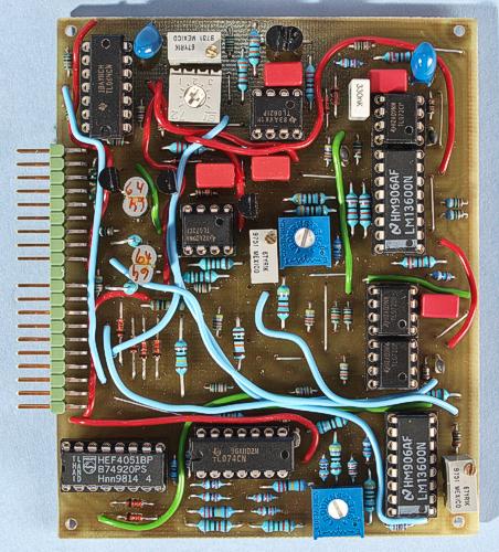
The prototype version of the board. There are a few differences compared to the final board.
This AMORE module combines a multimode VCF and a VCA on one board. The filter is basically a clone of the filter in the Oberheim SEM. However, this version uses the LM13600/13700 instead of the CA3080 and JFET op-amp buffers instead of discrete FET source followers. The filter has a 12 dB/oct. slope and offers lowpass, bandpass, highpass and notch response. There is voltage control over resonance and filter mode selection. The resonance on a state variable filter works somewhat backvards: There is full resonance when there is NO feedback. When you apply feedback, you lower the resonance. In the current version I have redesigned the circuit to allow for self oscillation. To achieve this, I supply full feedback by connecting the bandpass signal through a 33k a resistor, to get no resonance. Then I add the bandpass signal phase inverted through a VCA to raise the resonance allt the way to self oscillation. The schematics shows how it is done. Note that if you use the LM13700, you will have to raise the gain of the VCA slightly, to get self oscillation. You do this by increasing the 75k resistor.
The
board is plug compatible with the Minimoog
clone VCF + VCA, with the exception that this module lacks the
bypass feature on the VCA and adds the filter mode selector on a pin
that is unused on the Minimoog VCF + VCA. If you leave this pin
unconnected, the multimode filter defaults to lowpass response. Note
that in bypass mode, there is a special feature: If you select
bandpass mode, the filtered signal will be added to the direct
signal. This is handy if you want to use the filter for adding a
formant resonance to the sound. Note, however, that the wet/dry mix
is fixed at fifty-fifty. If you want control over the mix, you can do
the mixing externally with the VC-crossfade
module.
This is a nice-sounding filter and the module offers a
lot of functionality on a small board.
The
VCA on this board has two stages, which means that you can multiply
two different control signals. Normally one of them is an envelope
shaper and the other is some other form of amplitude modulation, like
tremolo or a foot pedal. The latter is the case on the Minimoog.
The
first stage of the VCA is built with discrete transistors and the
second stage uses one half of a LM13600/13700 OTA. The reason is of
course to result in an even number of OTAs, as the filter feedback
also uses one OTA.
Bill of materials
You
should have access to the parts in the general
bill of materials.
In addition, you need the following less
common parts:
No special parts needed.
Matching
The NPN transistor pair in the first VCA stage and the PNP pair in the filter exponential converter should be matched. You can use the AMORE Transistor Matcher for doing this. The VCA transistor pair is the one between the 470 ohm resistors, next to the AMORE connector. The PNP pair for the VCF is located at the very top, to the right of the oct/V trimmer. It's a good idea to glue the matched transistors together, to keep them roughly at the same temperature. If you can find them, and don't mind the cost, you can use matched dual transistors instead of manually matching regular transistors.
Trimming
There are six trimmers on the board. Two of them are for the VCA and the rest for the VCF.
Null VCA1
Measure the voltage at the output of VCA stage 1 while sweeping the VCA AM CV. Trim until the DC voltage variation is as small as possible.
Null VCA2
Measure at the VCA output with the VCA AM CV full-on and sweeping the VCA env CV. Trim until the DC voltage variation is as small as possible.
Null VCF1
Feed the filter with a triangle wave of fairly low frequency and monitor the waveform at the top of the two diodes to the left of the top LM13600/13700. Turn the resonance knob up fully. Adjust the filter cutoff knob to maximum resonance. You will see a waveform on the oscilloscope. Turn the resonance knob down until the waveform almost disappears and then adjust this trimmer to make the waveform symmetrical.
Null VCF2
Remove the input signal and adjust this trimmer for minimum DC variation while sweeping the filter cutoff knob.
VCF init F
Set the filter to lowpass response. Feed the filter with a 30 Hz triangle or sine wave and adjust this trimmer until the signal just disappears.
VCF oct/V
Set the filter to bandpass response. Feed the filter with a 100 Hz triangle or sine wave. Adjust the cutoff for maximum resonance. Feed the same control voltage to the keyboard tracking inputs (KOV) of both the filter and the VCO. Sweep the pitch CV and adjust the trimmer so that the waveform from the filter keeps roughly the same amplitude when the pitch changes. This means the filter tracks the VCO pitch.
Skill level required: MEDIUM
This module needs matching of transistors. Otherwise there are no particular difficulties and the circuit uses no hard to find parts.
|
Connector pin |
signal |
on this module |
|
1 |
1 oct/V |
VCF keyboard tracking |
|
2 |
in 1 |
VCA input |
|
3 |
CV 1 |
VCA AM CV |
|
4 |
CV 2 |
VCA envelope CV |
|
5 |
CV 3 |
not used |
|
6 |
-15 V |
-15 V |
|
7 |
out 1 |
output from VCA |
|
8 |
-1 V |
-1 V |
|
9 |
gnd |
gnd |
|
10 |
key |
- |
|
11 |
switch 1 |
not used |
|
12 |
switch 2 |
bypass VCF |
|
13 |
out 2 |
output from VCF |
|
14 |
+15 V |
+15 V |
|
15 |
+10 V |
not used |
|
16 |
aux output |
not used |
|
17 |
in 2 |
VCF input |
|
18 |
CV 4 |
VCF cutoff CV |
|
19 |
CV 5 |
VCF emphasis CV |
|
20 |
CV 6 |
VCF filter mode CV |