
Basic VCO
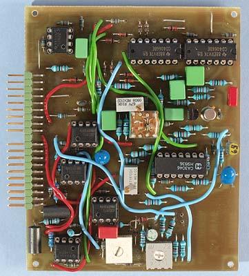
The Basic VCO is a half size AMORE board. This picture shows a prototype.
This is a fairly simple
VCO module which fits on a half size AMORE board. In addition to the
smaller number of parts, this VCO doesn't use any matched
transistors. In spite of this, the VCO has excellent temperature
stability and good quality waveforms.
The core of this module is
based on the ARP 4027-1 which was used in later ARP 2600s. The main
advantage of this VCO core is that it has excellent HF tracking
without any need for HF trimming. The exponential converter uses a
NPN/PNP transistor pair and a tempco resistor that are potted
together for best temperature stability.
Another feature of this
VCO core is that it is switchable between audio and LFO mode. So you
can use it either as an audio oscillator or a low frequency
modulator.
In addition to what the ARP 2600 offers, the
Bergfotron Basic VCO has the following:
Triangle wave
Sync
Voltage controlled waveform selector
Digitally controlled audio/LF switch
Digitally controlled mute function
Compared to other VCO modules, the Basic VCO does NOT offer:
Sine wave
Linear FM
Octave quantizer
The voltage controlled waveform selector is not intended for sweeping, as the waveform is undefined around the switching points. It's main purpose is for programmable waveform selection or for polyphonic use, where you want to gang several VCOs and control the waveforms on all of them from the same source.
Temperature stability
This VCO uses a NPN and
PNP transistor pair for the exponential converter. With two different
types of transistors, there is no point in trying to match these.
They should however be thermally coupled in order for the VCO not to
drift with temperature. I used a BC847 for the transistors. It's a
very inexpensive surface mount transistor pair consisting of one NPN
and one PNP transistor. For additional temperature compensation the
VCO uses a 2 kohm temperature compensation resistor. The ideal
temperature coefficient for this resistor is supposed to be 3300 ppm.
I used two 1 kohm surface mount resistors in series, one with 3000
ppm and one with 3900 ppm temperature coefficient. Testing of the
completed VCO yielded a slight under-compensation so maybe it would
have been better to use two 3900 ppm resistors instead. I mounted all
the surface mount parts (dual transistor + two resistors) in a small
circuit board on a component carrier which plugs into an ordinary 8
pin IC socket. The parts were potted with Araldite.
If you don't
require temperature stability, you can use an ordinary 2 kohm
resistor plus a BC550C and a BC560C transistor instead. These can be
soldered directly to the main circuit board.
This
swing-in graph was measured by letting the VCO warm up for at least 1
hour, tuning it carefully, switching it off for at least an hour,
turning it back on and immediately start to measure the tuning
(without re-tuning it). This procedure was repeated with the VCO
tuned in four different octaves. As you can see, it starts at near
correct tuning but goes severely flat for over 15 minutes while the
components warm up. You''ll have to wait half an hour before it is
completely in tune. After that it will however retain the tuning
quite well.
The waveforms
The Basic VCO has a
sawtooth core. The pulse wave is generated by a comparator in the
usual way. The triangle converter is the classic one transistor
folder. Usually with this design a glitch in the triangle wave is
unavoidable, as the reset of the sawtooth can never be instantaneous.
On this VCO the glitch is virtually eliminated, by adding the reset
spike from the VCO core to the triangle wave.
The module
generates three different waveforms that are available
simultaneously. On the main output you can select between sawtooth,
pulse and triangle wave by means of a control voltage. If you leave
this control input unconnected, the main out will output the sawtooth
wave. On the other two outputs, the triangle and pulse waves are
available at all times.
Sawtooth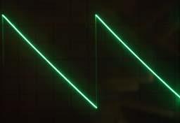
The sawtooth is the basic waveform that is produced by the VCO core. Measured on the oscilloscope at 1 kHz.
Triangle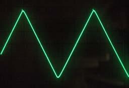
The triangle in audio mode at 1 kHz.
LFO triangle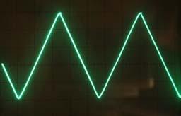
The triangle in LFO mode at circa 10 Hz.
Pulse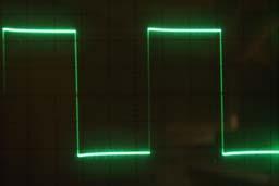
The pulse wave with traditional pulse width modulation at 1 kHz.
Bill of materials
You should have access
to the parts in the general bill of
materials.
In addition, you need the following less common
parts:
2 kohm 3500 ppm/°C temperature compensation resistor (1)
Matching
No matching required.
Trimming
These are the alignment steps for the Basic VCO:
1. Adjust the supply voltages to exactly 15.0 volts (on your power supply).
2. Set the frequency to around 1 kHz and adjust "tri adjust" to get the triangle wave as shape as good as possible.
3. Adjust the trimmer
"tri offset", to get the triangle wave symmetric around 0
volts. This will probably affect the waveform so you will have to
repeat step 2 and 3 a couple of times.
Check the triangle in LFO
mode at around 10 Hz too. It's difficult to get the triangle perfect
in both LFO and audio mode so if you want to use the module in both
modes it might be best to trim the waveform in LFO mode, as small
errors are less noticeable in audio mode.
4. Adjust "scale" to get exactly 1 octave per volt on the KOV input.
5. Adjust "freq. trim" to the desired base frequency so the VCO is in tune with other VCOs when fed the same control voltage.
6. The 39k resistor marked "see text" in the schematics is the glitch compensation for the triangle wave. The shown value was optimal for the parts I used. With other parts (especially the FET T1) a smaller or larger resistor value might be better. The goal is to reduce the glitch at the peak of the triangle waveform as much as possible.
7. The 270k resistor marked "see text" in the schematics compensates for the fact that the LFO mode changes the offset of the sawtooth somewhat, which affects the triangle waveform. If you have trouble trimming a good triangle waveform in both audio and LFO mode, you can try to change the value of this resistor. Note however that unsoldering this resistor tends to make IC8 (CA4066) fail. It's safest to clip on a grounding wire to the AUDIO/LF input on the edge connector before you solder.
Skill level required: LOW
This board contains a limited number of parts and it does not require matching of components. For best temperature tracking you should glue the tempco resistor and the exponential converter transistors together. This is not necessary if you will use it as an LFO only or if high temperature stability is not required. So with a little bit of patience, this module should be fairly easy to build.
The above schematic diagram (link) contains all circuitry on the module, except the supply decoupling.
Circuit board layout
The component placement
plan contains pairs of capital letters. These are supposed to be
connected with insulated wires.
As this module is a half size
board, I also included a full size layout with two identical boards
for those who want to etch several VCOs at once.
Circuit board layout two-on-one PCB
|
Connector pin |
signal |
on this module |
|
1 |
1 oct/V |
KOV |
|
2 |
in 1 |
sync |
|
3 |
CV 1 |
not used |
|
4 |
CV 2 |
FM |
|
5 |
CV 3 |
not used |
|
6 |
-15 V |
-15 V |
|
7 |
out 1 |
main output |
|
8 |
-1 V |
-1 V |
|
9 |
gnd |
gnd |
|
10 |
key |
- |
|
11 |
switch 1 |
mute main output |
|
12 |
switch 2 |
audio/LF |
|
13 |
out 2 |
triangle output |
|
14 |
+15 V |
+15 V |
|
15 |
+10 V |
not used |
|
16 |
aux output |
pulse output |
|
17 |
in 2 |
not used |
|
18 |
CV 4 |
PW CV |
|
19 |
CV 5 |
not used |
|
20 |
CV 6 |
waveform CV |