
Dual voltage controlled bandpass filter (AMORE)
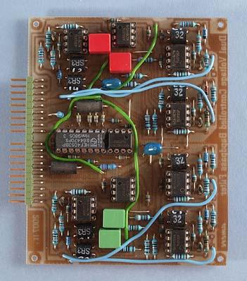
The prototype version of the board. There are a few differences compared to the final board.
The first AMORE
compatible module is a dual voltage controlled bandpass filter based
on LED/LDR optocouplers (better known as Vactrols). This filter is
primarily intended to create resonance peaks, so called formants,
which mimic properties of acoustical instruments. But since this
design is voltage controlled, and hence sweepable, it can be used in
many more ways.
With this filter you can voltage control the
resonance frequency, the filter bandwidth and the amount of resonance
(passband gain). The filter can only be used to create peaks and will
attenuate frequencies outside the passband. So you can't use it to
attenuate a selected frequency band like you can with a fully
parametric EQ.
This is a half size AMORE board and has been tested
and should not contain errors. I used LED/LDR optocouplers of the
types NSL-32 and NSL-32SR3 from Silonex Inc. Other optocouplers can
require changes in resistor values for optimum performance. Also,
there is a considerable unit variance in optocouplers so certain
combinations of CV-settings can cause the signal to distort or cut
out with certain optocouplers.
Note that there are four green and
four blue wire connections on the board in the photo above. These are
not shown in the component placement plan. The green wires connect
the points A, B, C and D. The blue wires connect the points CV A and
CV Q for each filter section.
Bill of materials
You should have access
to the parts in the general bill of
materials.
In addition, you need the following less common
parts:
STL
32SR3 Optocoupler (4)
STL 32 Optocoupler (4)
Trimming
No trimming is necessary or possible on this module.
Skill level required: MEDIUM
For this module you need to source suitable optocouplers and preferrably match the ones controlling the center frequency. Otherwise there are no particular difficulties and there is nothing to trim.
|
Connector pin |
signal |
on this module |
|
1 |
1 oct/V |
not used |
|
2 |
in 1 |
input to filter 1 |
|
3 |
CV 1 |
center frequency CV 1 |
|
4 |
CV 2 |
bandwidth CV 1 |
|
5 |
CV 3 |
passband gain CV 1 |
|
6 |
-15 V |
-15 V |
|
7 |
out 1 |
output from filter 1 |
|
8 |
-1 V |
-1 V |
|
9 |
gnd |
gnd |
|
10 |
key |
- |
|
11 |
switch 1 |
bypass filter 1 |
|
12 |
switch 2 |
bypass filter 2 |
|
13 |
out 2 |
output from filter 2 |
|
14 |
+15 V |
+15 V |
|
15 |
+10 V |
not used |
|
16 |
aux output |
not used |
|
17 |
in 2 |
input to filter 2 |
|
18 |
CV 4 |
center frequency CV 2 |
|
19 |
CV 5 |
bandwidth CV 2 |
|
20 |
CV 6 |
passband gain CV 2 |