
Minikorg filter (AMORE)
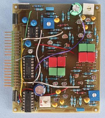
The prototype version of the board. There are a few differences compared to the final board.
This is a clone of the filter in
the Minikorg 700, 700S and 770. The filter contains both highpass and
lowpass sections with individual voltage control. On the Minikorgs,
the filter cutoff frequency is controlled by two sliders named
”Traveler”. These have a mechanical interlock to prevent
the highpass cutoff to be set higher than the lowpass and thus
letting no sound through.
On the Minikorgs there is no knob or
slider for filter resonance. Instead there is a two position switch
(three positions on the 770) named ”Bright”. This switch
selects between two degrees of resonance, with the addition of a
position for no resonance on the 770. So on the 700 and 700S you
can't turn resonance off completely and you can't control the
resonance for the highpass and lowpass sections independently. This
module mimics the 700/700s functionality, using AMORE switch 2. On
the original Korg filter there is an input named ”Expand”
that is fed by the envelope generator. On the AMORE module this is a
separate input although it too controls the cutoff frequency, just
like the Traveler input. The reason is that the Traveler input has a
somewhat limited frequency range (mimicking the slider throw) and a
smoothing filter. The Expand input is more sensitive and you can
choose which input you want to use for controlling the cutoff
frequency.
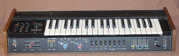
The
Minikorg 700S
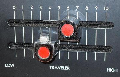
The
Traveler sliders on the Minikorg 700S.
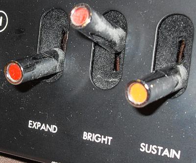
The
Expand switch adds envelope control to the filter and the Bright
switch increases the resonance.
This is a half size AMORE
board and has been tested and should not contain errors. The original
Minikorg filter runs on +20 and -10 volts. I mimicked this by using a
-5 V voltage regulator on the module, for establishing the filter's
ground potential at -5 V instead of 0 V.
Note that there are
several wire connections on the board in the photo above. These are
not shown in the component placement plan but instead marked with
capital letters. You just solder a wire between the two points that
have the same letter.
The four diodes for the diode ring of each
filter section should be matched. Using the resistance measurement
range of a DVM turned out to be erratic. Instead, you should connect
every diode in series with a 100 kohm resistor between +15 volts and
ground from the synth's power supply. Use lab cables and alligator
clips for this. Remember not to touch the diodes with your fingers
when you swap diodes for measuring. Measure the voltage drop over
each diode with a DVM and select the four diodes that are most
similar. There is no need to match the transistors used.
The
Expand inputs are connected directly to the filter core and have
somewhat higher sensitivity than the AMORE standard. Instead of the
usual 100 kohm resistor you'll want to use around 150 kohm if you use
these inputs.
Note that the 7905 voltage regulator is not
equipped with a heatsink. With the normal current draw of this board
this is OK – the 7905 will be just bearable to touch. Note
however, that if something on the board draws exessive current, the
7905 might get very hot. This might happen if there are shorts
between traces, parts are not soldered correctly or the 4066 is
faulty. Therefore, pay attention to the 7905 temperature whenever you
are working on the board.
Bill of materials
You should have access
to the parts in the general bill of
materials.
In addition, you need the following parts:
7905 -5 V voltage regulator (1)
Trimming
There are two trimmers in each filter section.
Resonance adjust
This
is for setting the fixed resonance. You can adjust it to your liking.
I don't know how they did the adjustment at the Korg factory.
Unmarked trimmer
There
is another trimmer in each filter section that frankly doesn't do
much. I retained it because the original has it. It adjusts the
cutoff frequency very slightly, but you can just leave it alone.
Skill level required: MEDIUM
For this module you need to select diodes for matching the diode ring. Otherwise there are no particular difficulties.
|
Connector pin |
signal |
on this module |
|
1 |
1 oct/V |
not used |
|
2 |
in 1 |
input to filter |
|
3 |
CV 1 |
Traveler highpass |
|
4 |
CV 2 |
Expand highpass |
|
5 |
CV 3 |
not used |
|
6 |
-15 V |
-15 V |
|
7 |
out 1 |
output from filter |
|
8 |
-1 V |
not used |
|
9 |
gnd |
gnd |
|
10 |
key |
- |
|
11 |
switch 1 |
bypass filter |
|
12 |
switch 2 |
Bright |
|
13 |
out 2 |
not used |
|
14 |
+15 V |
+15 V |
|
15 |
+10 V |
not used |
|
16 |
aux output |
not used |
|
17 |
in 2 |
not used |
|
18 |
CV 4 |
Traveler lowpass |
|
19 |
CV 5 |
Expand lowpass |
|
20 |
CV 6 |
not used |