
Voltage controlled phaser (AMORE)
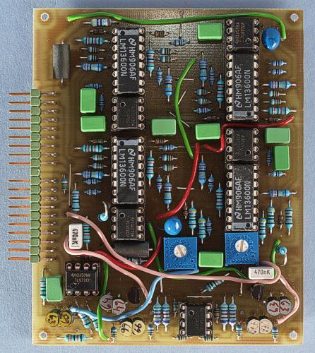
A prototype of the board.
Probably
the most successful of my pre-AMORE modules was the voltage
controlled phaser. Here is an AMORE-version with a few enhancements.
Like the old version, this is a voltage controlled phaser based on
the LM13600 OTA. The phaser core is the same and inspired by the
Electro Harmonix Small Stone. In order to use the linearizing diodes
in the LM13600, I had to make some changes to the circuit though.
This module contains eight phaser stages – twice as many as the
Small Stone. You can tap the signal after four or eight stages.
The
phaser stages are controlled by an exponential converter of the same
type that is used in many VCFs and VCAs.
A unique feature with
this module is that it has voltage controlled feedback, both after
four and eight stages. These give a different sound and you can even
use both at once, for even more sonic variation. Changing the
feedback to include more stages, creates more resonance peaks. There
is one peak/notch for every two stages. If you turn the feedback up
all the way, the phaser will oscillate.
To get many of the
classic phaser sounds, you must mix the dry (original) and wet
(phased) signal. There is no provision for this on the module, but
the VC-crossfader will be excellent for
doing this.
With
feedback after four stages and the phase knob at full, there are
resonance maxima at approximately 2.4 kHz and 18 kHz. There are
notches at 1.2 kHz and 6 kHz. With the phase knob turned to 7.5, the
peaks are at 720 Hz and 13 kHz, whereas the notches are at 360 Hz and
1.4 kHz
With feedback from stage 8, I measured the following
(frequencies approximate):
|
10 V CV |
7.5 V CV |
|
|
480 Hz |
140 Hz |
notch |
|
1 kHz |
300 Hz |
peak |
|
1.6 kHz |
480 Hz |
notch |
|
2.5 kHz |
720 Hz |
peak |
|
3.5 kHz |
1 kHz |
notch |
|
6.6 kHz |
1.7 kHz |
peak |
|
|
3.5 kHz |
notch |
|
|
15 kHz |
peak |
Obviously,
with full CV, the highest notch and peak are above the audible range.
Due to lack of board space, the voltage controlled feedback uses discrete VCAs, instead of 13600-based ones. Apart from using very little board space, these have another advantage in this application: They compress strong signals, which helps to avoid overdriving the phaser stages, which can produce nasty clicking or static in the sound. Because there was no room for offset trimmers for the VCAs, I have used 0.1% resistors and matched transistors. Some offset (CV bleedthrough) doesn't matter, as the signal is AC-coupled and you don't normally control the feedback amount with fast attacks.
I'm really satisfied
with the sound of this module. I was really surprised to find that it
is virtually noise-free. You would think that cascading eight OTAs
would create a lot of noise. But for some reason it doesn't.
I
also like the action of the feedback control. You can create
everything from slight resonances to aggressive overdriven sounds.
And by feeding it noise, you get the trademarked J.M. Jarre whooshing
sounds.
By using all eight stages, and no feedback, you can add
vibrato to any signal. This works best for signals which doesn't have
too high overtones though.
Bill of materials
You should have access
to the parts in the general bill of
materials.
In addition, you need the following less common
parts:
5.6 kohm 0.1 % resistors (4). Alternatively, you can hand-select 1 % resistors.
Matching
It is advisable to hand match the two transistor pairs next to the 5.6 kohm resistors at the bottom of the board. The PNP pair in the bottom left corner should be matched too. You can use this transistor matcher.
Trimming
There are only two trimmers on this board:
VCA offset 1 &
2
First adjust the offset null trimmer that is closest to the
centre of the board, with no input signal. Set both feedback CVs to
off (no CV voltage). Measure the 4 stage output of the phaser and
adjust the trimmer so there is as little DC change as possible when
you sweep the phase CV. Next, do the same with the second offset null
trimmer but measure at the 8 stage output.
Skill level required: MEDIUM
There isn't really anything particularly difficult on this module but you need to match transistors. The board is a bit densely populated but as long as you get parts of the right size, this shouldn't cause problems.
|
Connector pin |
signal |
on this module |
|
1 |
1 oct/V |
not used |
|
2 |
in 1 |
input |
|
3 |
CV 1 |
not used |
|
4 |
CV 2 |
not used |
|
5 |
CV 3 |
not used |
|
6 |
-15 V |
-15 V |
|
7 |
out 1 |
8 stage output |
|
8 |
-1 V |
not used |
|
9 |
gnd |
gnd |
|
10 |
key |
- |
|
11 |
switch 1 |
not used |
|
12 |
switch 2 |
not used |
|
13 |
out 2 |
4 stage output |
|
14 |
+15 V |
+15 V |
|
15 |
+10 V |
not used |
|
16 |
aux output |
not used |
|
17 |
in 2 |
not used |
|
18 |
CV 4 |
phase CV |
|
19 |
CV 5 |
feedback 4 CV |
|
20 |
CV 6 |
feedback 8 CV |