
Building the AMORE Starter Kit
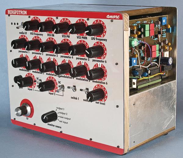
This is the AMORE Starter Kit with the Minikorg VCF board in operation.
To get started with AMORE modules you should first build the AMORE Starter Kit. This is a set of circuit boards that contain all you need to test and run an AMORE module. It can be used as service equipment but it can also be used as the basis for a standalone synth. The Starter Kit consists of three circuit boards: The first is cut up in four parts for mounting potentiometers and jacks. In addition to this, there is a motherboard with power supply and the standard connector for the AMORE module. Finally there is a board containing a full blown VCO and a simple LFO. This board is mainly intended as a signal generator when working on modules like filters and VCAs but could also be used as a sound- and modulation source in a standalone synth. This board is optional, if you don't need the functionality.
You use the
Starter Kit for testing and troubleshooting your new AMORE modules.
As the Starter Kit is already tested, you can rule out errors in the
pot/switch wiring, and such, when your module isn’t working.
This simplifies the process of getting the boards functional. You
also use the Starter Kit for trimming/calibrating the boards. When
all modules are built, you use the Starter Kit for
calibrating/servicing existing modules. It’s much easier to
take a board out of the synth and put it in the slot on the Starter
Kit for service than to put the entire synth on the workbench. In
addition, you can use the Starter Kit with a board of your choice as
a full blown module to your modular synthesizer. This is a great way
to try out a new module and hear how it sound together with existing
modules. You can take even the Starter Kit plus an AMORE module of
your choice with you to a studio or somewhere else, as it is a small,
portable unit that is self-contained.
The Starter kit replaces the
exerciser, that I described
earlier.
The motherboard
The
Starter Kit is based around a kind of motherboard (PCB1) that
contains the power supply and the standard AMORE connector. On this
board the output jacks and the inputs potentiometers are mounted
directly. In addition there are solder connections for the needed
switches. There are switches for the two switch functions on the
AMORE modules. In addition there is a three way switch for each
signal input that selects between DC, AC and overdrive mode for that
input. The latter doubles the gain to test the headroom/overdrive
characteristics of the module. All the CV and modulation amount
potentiometers plus the rest of the jacks are mounted on four
separate daughterboards (PCB3 – PCB6). These boards are
connected to the motherboard with connectors made from header strips.
The power supply on this board delivers highly stabilized -15,
+15 and +10 volts at up to circa 1 ampère each. So this board
can supply an entire medium-sized synth and not just the Starter Kit.
In addition there is circuitry for generation of -1 volts and
debouncing for the gate button, whick outputs a gate signal on a
separate jack. This is useful for testing envelope generators and
similar functions. There is an unused op-amp buffer that I used for
buffering a 15 turn potentiometer which is used for precision CVs
during testing and servicing modules. The board has connections for
an output selector switch (optional) that makes it easy to monitor
the different outputs.
You need three separate transformer
windings to power the motherboards. Most transformers have two
separate windings so you need one such transformer with 18 volts per
winding and one transformer with one 15 volt winding. The power
rating on the transformers depend on how many modules you want to
power with the power supply. For just the Starter Kit, around 10 VA
per winding should be enough. Best is to use at least 20 VA per
winding, so you can use the power supply up to it's current limit.
The pot/jack board
This board is supposed to be cut up in four ”slices” after etching and drilling. The slices are used as follows:
PCB3:
Contains the six pots for the modulation. For each pot there is an
op-amp circuit that allows the modulation to go both positive and
negative.
PCB4: Contains the six pots for fixed CV.
PCB5:
Contains the six modulation jacks plus the two signal input
jacks.
PCB6: Contains the headphone amplifier plus jacks for
headphones, line out, external input and gate signal output.
The signal generator board
To be able to test
AMORE boards like filters and VCAs, you need a signal generator that
delivers waveforms with the correct amplitude etc. This board (PCB2)
contains a full blown VCO, which is a clone of the VCO in the ARP
2600. This VCO delivers sawtooth, pulse and triangle waves on
separate jacks. There are inputs and amount knobs for frequency
modulation and pulse width modulation. There is also a switch that
changes the VCO frequency range from audio to LFO so you can use it
for modulation, just like on the ARP 2600. But in addition, there is
also a separate non-voltage controlled LFO which outputs triangle and
square waves on separate jacks. This LFO has it's own rate knob.
The
signal generator board is fully self-contained, with all
potentiometers and jacks on-board. It only needs an external power
supply and there is a dedicated connector for this on the
motherboard. You could even use this board as a VCO/LFO board in a
standalone synth. Built according to the description it does not
feature temperature compensation, however. If you require this, you
could substitute the 2 kohm resistor with a 2 kohm tempco resistor
and put this in thermal contact with the PNP/NPN transistor pair
nearby.
The Basic VCO module is plugged into the AMORE connector and ready to be used.
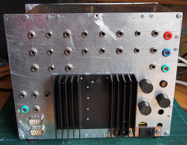
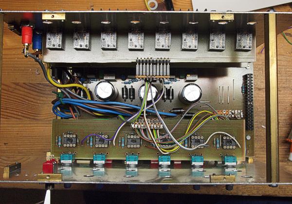
The Starter
Kit back panel. The top row of jacks is for the signal gerenator
board. The next row are the modulation inputs and signal inputs to
the AMORE board. The third row is the gate out, external in, line out
and headphone output on PCB 6. The jacks to the left of the heatsink
are the AMORE outputs on the motherboard. Below is a ground jack and
the jack for the optional 15 turn CV knob. The DB-9 connectors are
for connecting expansion units like the AMORE
Exerciser and currently only carry the supply voltages.
To the
right of the heatsink there are the three fuse holders and banana
jacks for all the supply voltages.
Schematics signal generator board
Circuit board layout motherboard
Circuit board layout pot/jack boards
Circuit board layout signal generator board
Component placement motherboard
Component placement pot/jack boards
Component placement signal generator board
Construction
Because the boards
contain both panel mounted components (potentiometers) and rear panel
mounted jacks, it is best to find or construct a box with the correct
depth. There are solder pads for two different kinds of
potentiometers. The large holes fit many different types, whereas the
small holes fit certain potentiometers from Alps and some other
manufacturers. The required depth of the box will depend on the
potentiometers used. I used Alps pots with a 1 mm shim on the pots.
For this, the correct depth of the box was 103 mm. If you have a
slightly deeper box, you can compensate with thicker shims.
The
motherboard must be mounted 15 mm to the right of the other boards,
to give room for the AMORE module in the connector. It makes sense to
mount the boards above each other, with the signal generator board on
top. I recommend 25 mm spacing between the boards. There will be a
total of four tiers and below the motherboard there needs to be room
for the transformers and the mains wiring. I mounted all the mains
components, including the mains socket and switch on the bottom
plate. The secondary windings from the transformers are connected to
the rest of the circuits with a multipole connector (6 poles needed),
so I can easily remove the mains unit for servicing. Don't forget to
add fuse holders in series with the transformer windings. Use 2 A
quick blow fuses for transformers over 20 VA per winding. The power
supply has short circuit protection that folds back the current to
500 mA if the load exceeds around 1,2 A. Note that if the chosen
transformer can't deliver 1,2 A, you should change the current
limiting circuit accordingly. In that case you'll have to consult the
datasheet for the 723 voltage regulator IC.
As usual, begin with
mounting wire links and then small parts like resistors etc. The
power transistors should be mounted on a heatsink on the back of the
box. Don't forget to use insulators between the transistors and the
heatsink. It is best to solder the power transistors to the board
after they are mounted on the heatsink and both the board and the
heatsink are mounted in the box.
The motherboard should be
supported in the connector end and not just hanging in the pots and
jacks. Otherwise the latter will be strained when you plug in and
pull out the AMORE modules. Drill holes in the motherboard for
support studs where the etched markings are.
The signal generator board can be supported by the potentiometers and jacks, as there is nothing straining it. If you want the jacks in a different place, you can saw the board apart in the area where there are no components or traces. There are etched pads for connectors between the jack part and the rest of the board. These are only used if you cut the board in two pieces. This module uses the CA3046 transistor array, which can be somewhat difficult to find but is in fact still available from specialist suppliers. One of them is Das Musikding in Germany. They are not expensive, so buy some extra for future modules while you're ordering!
Bill of materials
You should have access
to the parts in the general bill of materials.
In
addition, you need the following parts:
NE5532
Dual op-amp (1)
LM723 Voltage regulator IC (3)
TIP3055 Power
transistor (3)
1N5406 Power diode (12)
LED (3)
100 kohm lin
potentiometers (6)
50 kohm lin potentiometers (2)
10 kohm lin
potentiometers (8)
100 kohm log potentiometers (1)
50 kohm log
potentiometers (2)
5 kohm log potentiometers (1)
Rotary switch
(1)
SPDT toggle switch (2)
1-0-1 sinle pole toggle switch
(2)
SPDT pushbutton switch (1)
3,5 mm stereo jack for circuit
boards (23)
Banana jacks (5)
Male DB-9 connector (2)
Single
row circuit board connectors (2.54 mm pitch), male
Single row
circuit board connectors (2.54 mm pitch), female
2 x 20 pin
circuit board connector (2.54 mm pitch), female (1)
Knobs for
potentiometers (20)
Knob for rotary switch (1)
Heat
sink
Insulating washers for power transistors
Thermal
compound
Mains transformer 2 x 18 V 50 VA (1)
Mains transformer
2 x 15 V 30 VA (1)
Fuse holder (3)
2 A quick blow fuse
(3)
Mains switch (1)
Mains inlet (1)
Veroboard
(stripboard)
Suitable insulated wire
Suitable case, screws,
nuts etc.
Trimming
There are five trimmers on the signal generator board:
Saw offset
Adjust
this so that the VCO sawtooth wave is symmetric around 0 volts.
Tri adjust
Adjust
this to make the triangle waveform look as good as possible.
Tri offset
Adjust
this so that the VCO sawtooth wave is symmetric around 0 volts. Note
that adjusting the offset will change the waveform so you will have
to readjust these two settings for the triangle wave until both the
waveform and the offset is OK.
Freq trim
Adjust
this so that the VCO has a frequency range of approximately 20 Hz to
20 kHz when turning the frequency knob all the way.
Scale
This
will only have to be adjusted if the VCO is supposed to track 1
octave/volt. For use as a test tone generator this is normally not
necessary. If you require this, you will have to connect a voltage of
exactly 1, 2, 3, 4, 5 volts etc. to the KOV input and check that the
frequency doubles for every volt.
Skill level required: LOW
There isn't anything
particularly difficult on this board.
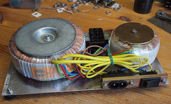
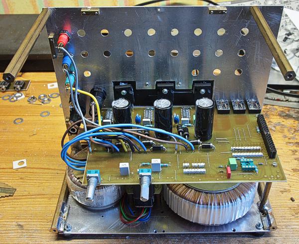
I mounted the mains transformers, socket and switch on the bottom plate. The secondary windings are connected to the motherboard via the connector between the transformers. This way, the mains part can easily be removed for access to the underside of the motherboard.
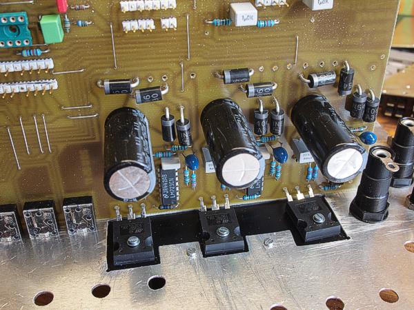
The motherboard is mounted to the rear panel and the power transistor legs are shaped so they fit in the holes and the transistors have good contact with the heat sink (black surface in the picture). The transistors are screwed to the heatsink (holes drilled and tapped in advance).
This is the underside of the motherboard. The power transistors are about to be soldered.
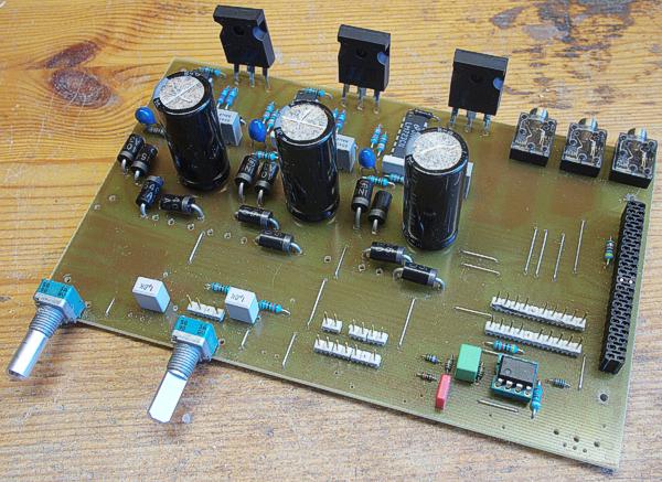
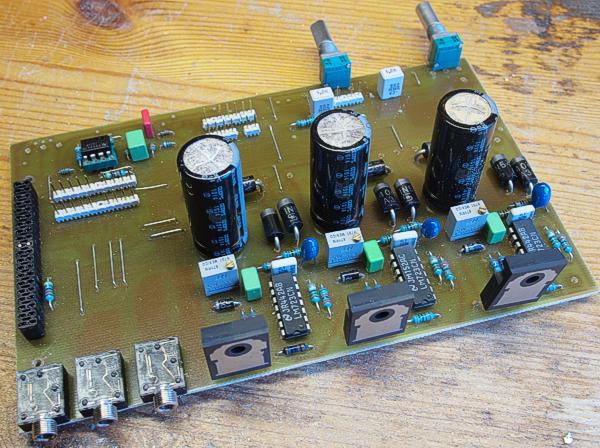
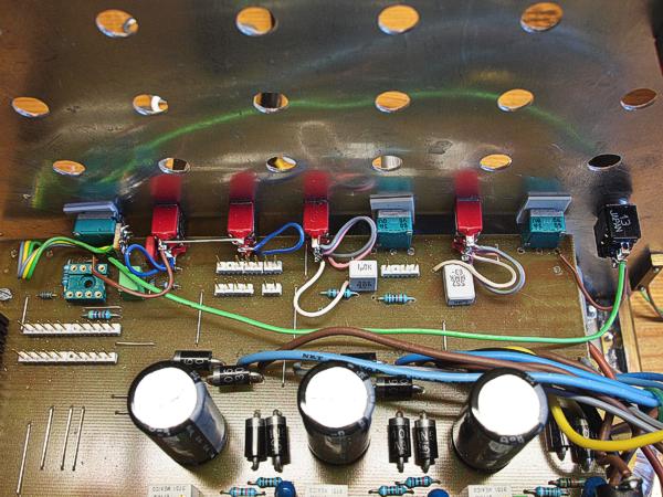
The motherboard has been removed from the box. The power transistors are now soldered.
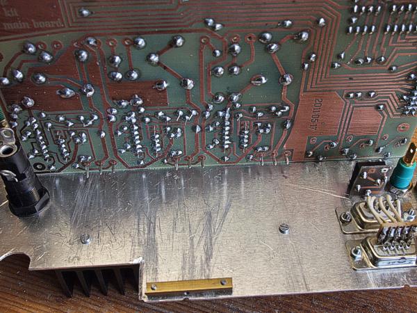
The motherboard seen from the back.
Here the wires for connecting the motherboard to the transformers, the fuse holders and the banana jacks on the back panel have been soldered.
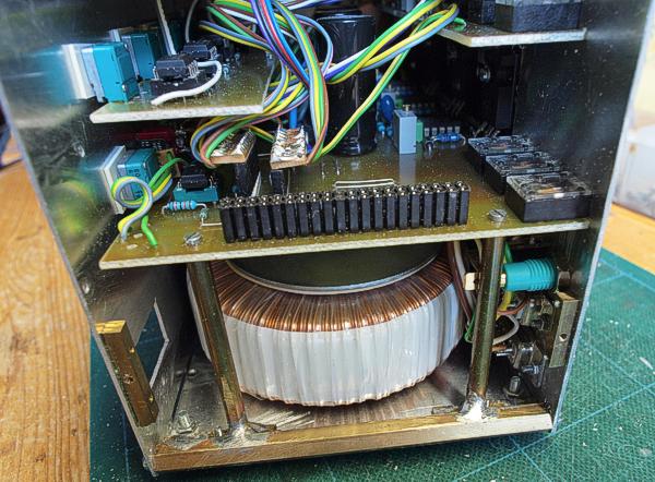
The studs that support the motherboard on both sides of the AMORE connector can be seen here (below the motherboard).
The front panel switches have been connected to the motherboard. Note that the final version of the motherboard has some improvements which don't appear on this prototype.
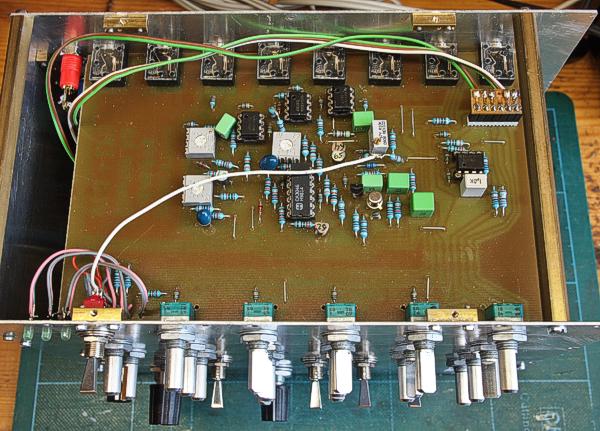
Here the boards for the modulation pots (PCB3) and jacks (PCB5) have been mounted. Note the plugs and wires that connect them to the motherboard. I solder small strips of Veroboard on the female connectors, to solder the wires to.
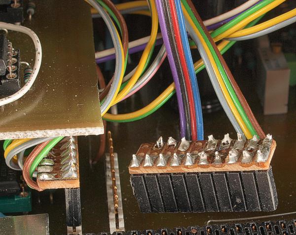
A close-up of the plugs. The required length is sawed from a longer connector. Note the small piece of Veroboard (three rows of holes) soldered on top of the connector. The wires are soldered to the other end of the Veroboard.
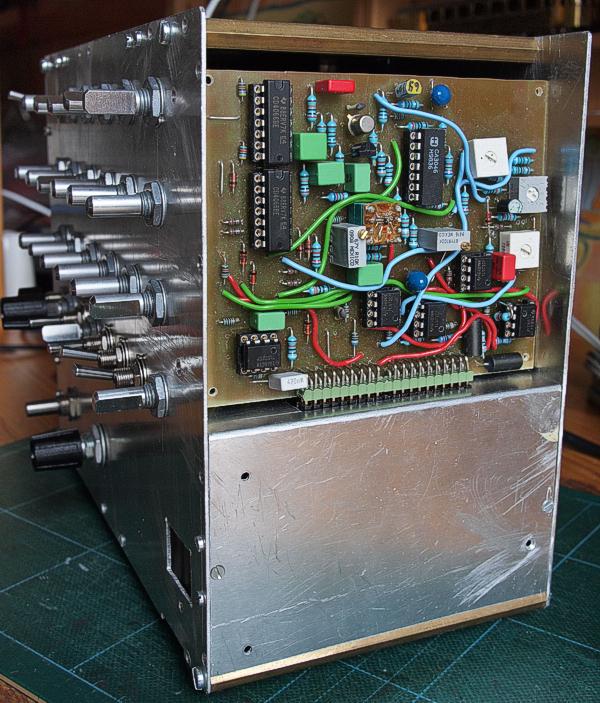
The signal generator board is the last one to be mounted.
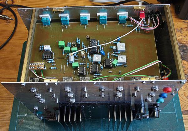
The signal generator board seen fron the front.
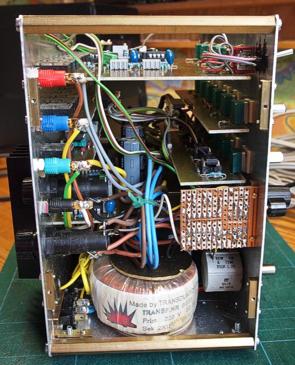
Here all boards can be seen from the left end of the unit. The circuits on the Veroboard to the right in this prototype have been integrated on the motherboard in the final version. The pot below the Veroboard is a 15 turn type that is used for generating precision CVs. There is an unused op-amp buffer on the motherboard that can be used to buffer the voltage from the pot. An extra jack has to be added to the back panel if you want to add this feature.
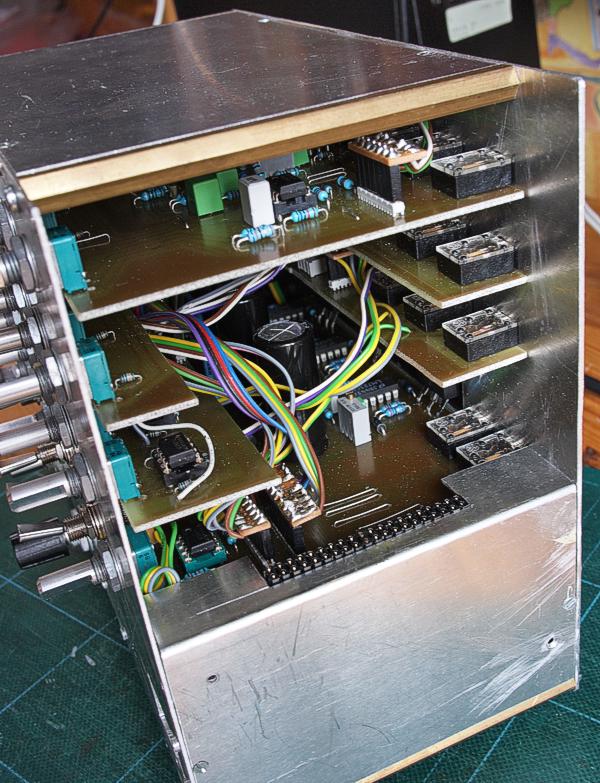
The other end with no module in the AMORE connector.
Front panel construction
The
Starter Kit uses my new method for making front panels. As you have
seen from the pictures above, the pots and switches are mounted on
aluminum plate that is a part of the case structure. For the actual
front panel, there must be some kind of spacer, to conceal the nuts
and threads on the pots and switches. The actual front panel is then
made of clear polycarbonate plastic and the graphics is on a photo
paper printout behind the clear plastic. The advantage with this
design is that you can fairly easily change/upgare the graphics (just
replace the printout) and the clear plastic protects the graphics.
As
you can see in the pictures, I used wood for the spacer layer. With
the switches and pots I use, this layer should be 8 mm thick and
that's a standard wood dimension.
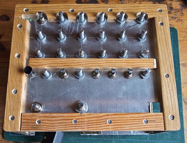
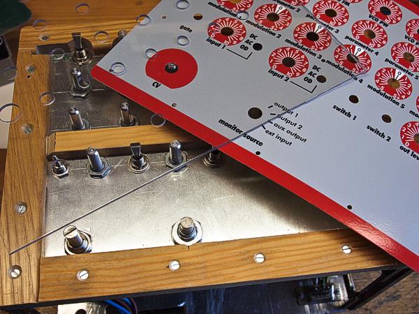
Here the wood spacers are in place. As you can see, they are screwed to the aluminum case with countersunk screws.
The clear plastic and the graphics printout are fixed with very small wood screws. You can see them along the edges and there is one between ”mudulation 3” and ”modulation 4” too.
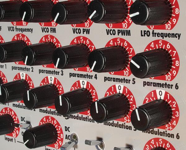
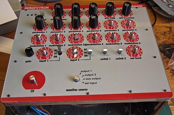
A closeup of the finished panel.
The AMORE standard connector on the motherboard
|
Connector pin |
signal |
|
1 |
1 oct/V |
|
2 |
in 1 |
|
3 |
CV 1 |
|
4 |
CV 2 |
|
5 |
CV 3 |
|
6 |
-15 V |
|
7 |
out 1 |
|
8 |
-1 V |
|
9 |
gnd |
|
10 |
key |
|
11 |
switch 1 |
|
12 |
switch 2 |
|
13 |
out 2 |
|
14 |
+15 V |
|
15 |
+10 V |
|
16 |
aux out |
|
17 |
in 2 |
|
18 |
CV 4 |
|
19 |
CV 5 |
|
20 |
CV 6 |