
Minimoog clone VCF + VCA mk II (AMORE)
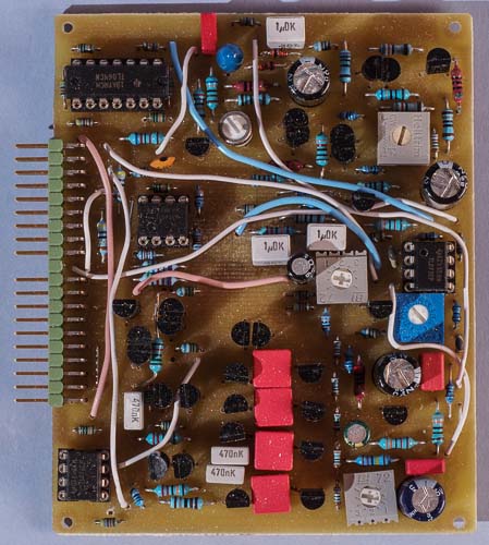
The prototype version of the board. There are a few differences compared to the final board.
This
AMORE module combines clones of the Minimoog VCF and VCA on one
board. The core circuits are the same as on the Minimoog
clone VCF and VCA mk I. The main difference is that I managed to
fit the circuits on a half size board in this version. Apart from
that, there are two electrical differences: This version uses a
simple VCA to achieve voltage controlled resonance. On the mark 1, on
the other hand, this is done by means of a Vactrol type optocoupler.
Secondly, the bypass feature on the mk I has been omitted in this
version.
The core of this filter is almost exactly the same
circuit as in the Minimoog. Only a couple of minor changes had to be
made, to be able to run it on +-15 volts, instead of +-10 volts.
These changes were developed by René
Schmitz.
To get the best performance, I matched all transistors and capacitors in the transistor ladder. Of course, the transistors for the differential amplifier were also matched. This filter really sounds sweet. It has the classic Minimoog sound and noise is quite low. I don't have genuine Minimoog to compare, but maybe my filter is a little quieter thanks to the BC550C low noise transistors.
The Minimoog VCA is
using only discrete transistors as active components. It has two
cascaded stages that can be voltage controlled individually. After
that there is a discrete buffer amplifier.
In the Minimoog, the
first stage is controlled by the envelope generator and the second
stage is controlled by the foot pedal. I reversed this, as having the
EG on the second input gives much better signal to noise ratio. The
foot pedal input is intended for use with type of amplitude
modulation except envelopes in my module.
To get the best
performance, I matched all transistor pairs. I also used polyester
caps in the signal path. There are no electrolytic caps in the signal
path in my version of the VCA. The Minimoog has electrolytic output
DC blocking caps.
I changed some of the resistor values so that
the VCA would run as well as possible on +-15 volts supply.
This is not a very high
fidelity VCA, but the noise level is quite low. There is some
distortion, but not more than most other good VCAs, I suppose. There
is also some CV feed through that causes a slight click when very
short attack times are used. This is normally masked by the input
signal. Maybe it even adds to the punchiness of the sound.
I have
trimmed the offset to get no DC shift before the DC blocking
capacitor. But there is some AC-coupling of the CV signals anyway.
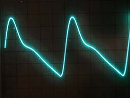
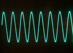
Example waveforms
Here are some examples with the filter fed a 1 kHz sawtooth from the Dual VCO and the filter cutoff set to roughly 4 kHz. Other ratios between oscillator frequency and filter cutoff frequency will of course produce different waveforms.
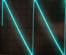

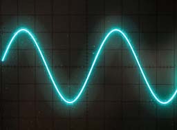
This is the effect of varying the cutoff frequency. As you can see, the amplitude is reduced when the cutoff frequency is lowered.
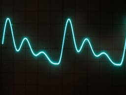
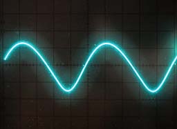
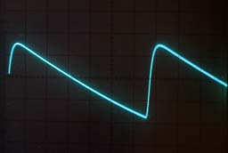
The effect of increasing resonance. As you can see, the amplitude gets lower when the resonance is increased.
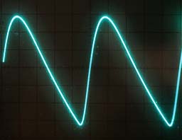
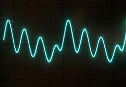
The resonance turned up to self oscillation. The first picture is with input signal (same as above examples) and the other are with no signal – just the filter oscillation.
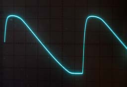
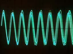
Overdriving the filter's input results in soft clipping.
Building the module
Bill of materials
You
should have access to the parts in the general
bill of materials.
In addition, you need the following less
common parts:
5.62
kohm 0.1% resistors (2)
20 ohm trimmer (1)
10 µF
non-polar electrolytic capacitor (1)
Matching
This
module needs matching of transistors, using the Bergfotron
transistor matcher. See circuit diagram for information on which
transistor pairs need matching.
There might be some advantage to
also matching the four 22n capacitors.
Trimming
There are two trimmers,
marked balance 1 and 2, for nulling the DC offset of the VCA. Measure
before the DC blocking capacitor at the output and adjust the
trimmers so there is minimal change in the DC voltage when you sweep
both CVs.
The VCF has three trimmers. ”Regen cal”
adjusts the maximum resonance. Adjust it so that the filter just
starts to oscillate at some fairly low cutoff frequency. This
adjustment is done according to personal taste. "Scale"
sets the volts per octave scaling of the filter. Set the filter to
self oscillation and feed connector pin 1 with exactly 1, 2, 3, 4
volts and measure the frequency. Trim until you get a doubling of the
frequency for each volt's increase. "Range" adjusts the
cutoff frequency and can be set to taste, so the cutoff knob on the
front panel covers the range you want.
Skill level required: MEDIUM
The board is rather densely populated. Otherwise there are no particular difficulties and the circuit uses no hard to find parts.
|
Connector pin |
signal |
on this module |
|
1 |
1 oct/V |
VCF keyboard tracking |
|
2 |
in 1 |
VCA input |
|
3 |
CV 1 |
VCA AM CV |
|
4 |
CV 2 |
VCA envelope CV |
|
5 |
CV 3 |
not used |
|
6 |
-15 V |
-15 V |
|
7 |
out 1 |
output from VCA |
|
8 |
-1 V |
not used |
|
9 |
gnd |
gnd |
|
10 |
key |
- |
|
11 |
switch 1 |
not used |
|
12 |
switch 2 |
not used |
|
13 |
out 2 |
output from VCF |
|
14 |
+15 V |
+15 V |
|
15 |
+10 V |
not used |
|
16 |
aux output |
not used |
|
17 |
in 2 |
VCF input |
|
18 |
CV 4 |
VCF cutoff CV |
|
19 |
CV 5 |
VCF emphasis CV |
|
20 |
CV 6 |
not used |