
Dual VCO
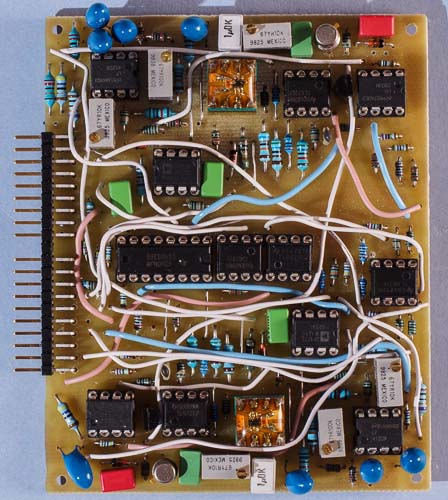
The Dual VCO fits two VCOs on just a half size AMORE board. This picture shows a prototype.
Here
we have two high quality voltage controlled oscillators on a
surprisingly small board. And I achieved this without resorting to
custom ICs or surface mount technology. These voltage controlled
oscillators have a core that is similar to the one used in later
Minimoogs. But with today's op-amps and some other changes, it offers
even better stability. The exponential converter uses a conventional
NPN transistor pair and a tempco resistor that are potted together
for best temperature stability. This results in stable tuning with
low drift, fast swing-in after switch-on and good temperature
stability. Both oscillators offer a choice of sawtooth or pulse wave
with digitally controlled waveform selection.
To facilitate
tuning of the oscillators, there is a built-in tuning indicator. It
powers a LED that blinks with a rate that is the differende between
the two VCO's frequencies. Handy if you need to check/adjust tuning
or detuning before you start playing.
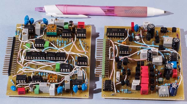
The VCO cores on this
circuit board are identical to those on the Minimoog
style VCO and the Woodwind VCO.
Note that this board is plug compatible with all the other AMORE
VCO boards. Differences in the feature sets
between boards only mean that controls for unavailable features do
nothing.
The Bergfotron Dual VCO has the following functions:
Sawtooth and pulse wave
Internal sync – digitally activated
Linear FM
Digitally controlled waveform selectors
Output for tuning indicator LED
Together with the Minimoog clone VCF and VCA board, the Dual VCO offers a complete, high quality bread and butter synthesizer voice. You just have to add LFO and envelope generators.
The built-in sync feature synchronises VCO 1 to VCO 2 when activated. You set VCO 2 to the desired pitch and use the sound from VCO 1. The timbre of the sound will vary, depending on how much higher pitch VCO 1 is set to. The pitch will however be constant and the same as VCO 2's pitch. You should not set VCO 1 to a lower pitch than VCO 2 when sync is on. This will only result in a weaker signal and no shift in timbre. Sweeping the VCO 1 pitch upward with an envelope generator creates the classic sync sound.
A
compact basic synthesizer voice with many possibilities
Temperature stability
For additional temperature compensation the VCO uses a 1 kohm temperature compensation resistor. The ideal temperature coefficient for this resistor is supposed to be 3300 ppm. I used one with 3000 ppm temperature coefficient. This VCO uses the Bergfotron standard socket for the exponential converter transistor pair and temperature compensation resistor. Here you plug in a component carrier where you solder the transistor pair and tempco resistor of your choice. These should be in thermal contact and preferably potted together for lowest temperature drift. I used surface mount parts (dual transistor + tempco resistor) soldered to a small circuit board on the component carrier which plugs into the 8 pin IC socket. The parts were potted with Araldite. If you don't use surface mount parts, you can solder the dual transistor and tempco resistor directly on the circuit board. For practical reasons I recommend the solution with the component carrier even for these though.
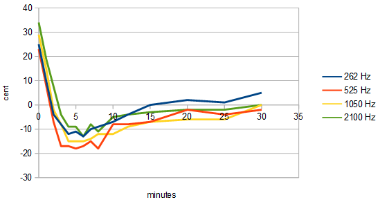
This
swing-in graph was measured by letting the VCO warm up for at least 1
hour, tuning it carefully, switching the power off for at least an
hour, turning it back on and immediately start to measure the tuning
(without re-tuning it). This procedure was repeated with the VCO
tuned in four different octaves. As you can see, it starts very
slightly sharp but immediately goes slightly flat for a couple of
minutes while the components warm up. This deviation is however very
minor, and already after 10 minutes it is almost in tune. After
warm-up there is essentially no drift. However, I have not been able
to measure the stability over varying ambient temperatures yet.
These
measurements were made with the AMORE Starter Kit and also include
the warm-up and temperature stability of the AMORE power supply
(which is very good).
You might have expected that the swing-in
behaviour would be exactly the same as on the other VCOs that use the
same VCO core. Well, I suppose the slight difference is due to
component variations and possibly the matching of the transistors in
the exponential converter.
The waveforms
This module produces the classic synth waveforms sawtooth and pulse. Measured on the oscilloscope at 1 kHz.
Sawtooth
Sawtooth with sync activated


Pulse
Sound clips
These sound clips are recorded with just the Dual VCO, the Minimoog VCF, two LFOs and a mixer module.
PWM example Here the two VCOs are set to pulse wave and mixed. Pulse width modulation is applied from the LFO. Filter cutoff and resonance is controlled manually.
Sync example This is an example of using the built-in sync. VCO 1 is set to sawtooth, it's frequency is modulated with an LFO and it's output is routed to the VCF. Filter cutoff is controlled manually. No resonance on the VCF.
Building the module
There are a few things to note when building and integrating this module.
The Waveform selector for VCO 2 is a standard AMORE current input. You will need to add an external 100k resistor to control it with 0 and 10 volt for selecting waveform. This in contrast to waveform select for VCO 1 and sync on/off, which are digital inputs and can be controlled with 0 and 10 volts directly. The reason for this is that the AMORE standard allows for only two digital inputs.
The tuning indicator output is open collector. This means the LED must be connected to +15V at the other end (the longer pin).
The two VCOs have additional filtering on the supply lines, to prevent soft synchronisation or other interaction of the two VCOs. Make sure to make the interconnecting wires the same way as in the component placement plan. There are pads marked N and N2. These are for the negative supply. Connect the Ns with a wire and the N2s with two wires, each running from the middle pad to ones in the corners.
I have made modules with the exponential converter transistors and the temperature compensating resistors on 8 pin component carriers. This solution allows for better thermal coupling between these parts but is optional. You can solder these parts directly to the circuit board if you prefer.
Bill of materials
You should have access
to the parts in the general bill of
materials.
In addition, you need the following less common
parts:
8
pin DIL component carrier
1 kohm 3500 ppm/°C temperature
compensation resistor (1)
Dual NPN transistor or a hand-matched
transistor pair (1). The 2SC1583 is a good choice, if you can find
it. I have used a SMD type transistor pair and SMD type tempco
resistor mounted on a small circuit board on a 8 pin component
carrier. Even if you use conventional parts, it is a good idea to
mount them on a component carrier and cover them with heat insulating
material. I used epoxy glue for this.
2N4391 or compatible FET.
This must be a fast switching, low Rds-on type.
LF412 dual OP-amp
(1). Other decently fast op-amps with low offset and drift can be
used.
OP177 single precision op-amp (1). Other ultra-low drift
op-amps can be used. This one doesn't have to be fast.
Matching
No hand-matching required if you use a matched transistor pair.
Trimming
These are the alignment steps for the Minimoog style VCO core:
1. Adjust the supply voltages to exactly 15.0 and 10.0 volts (on your power supply). Note that this module uses the 10 V supply for the tuning-critical parts, so his has to be very stable. Using the AMORE power supply is recommended.
2. Adjust "scale" to get exactly 1 octave per volt on the KOV input.
3. Adjust the HF-trimpot to get exactly 1 octave per volt at higher frequencies (above 2 kHz).
4. Adjust "init freq." to the desired base frequency so the VCO is in tune with other VCOs when fed the same control voltage.
Skill level required: MEDIUM
This board is quite densely populated but does not require matching of components, if you use a dual transistor for the exponential converter. For best temperature tracking you should glue the tempco resistor and the exponential converter transistors together.
The component placement
plan contains pairs of capital letters. These are supposed to be
connected with insulated wires.
|
Connector pin |
signal |
on this module |
|
1 |
1 oct/V |
KOV |
|
2 |
in 1 |
lin FM VCO 1 |
|
3 |
CV 1 |
not used |
|
4 |
CV 2 |
frequency CV VCO 1 |
|
5 |
CV 3 |
pulse width CV VCO 1 |
|
6 |
-15 V |
-15 V |
|
7 |
out 1 |
VCO 1 out |
|
8 |
-1 V |
not used |
|
9 |
gnd |
gnd |
|
10 |
key |
- |
|
11 |
switch 1 |
saw/pulse VCO 1 |
|
12 |
switch 2 |
sync on |
|
13 |
out 2 |
VCO 2 out |
|
14 |
+15 V |
+15 V |
|
15 |
+10 V |
+10 V |
|
16 |
aux output |
tuning led |
|
17 |
in 2 |
lin FM VCO 2 |
|
18 |
CV 4 |
frequency CV VCO 2 |
|
19 |
CV 5 |
pulse width CV VCO 2 |
|
20 |
CV 6 |
saw/pulse VCO 2 |