
Advanced VCO
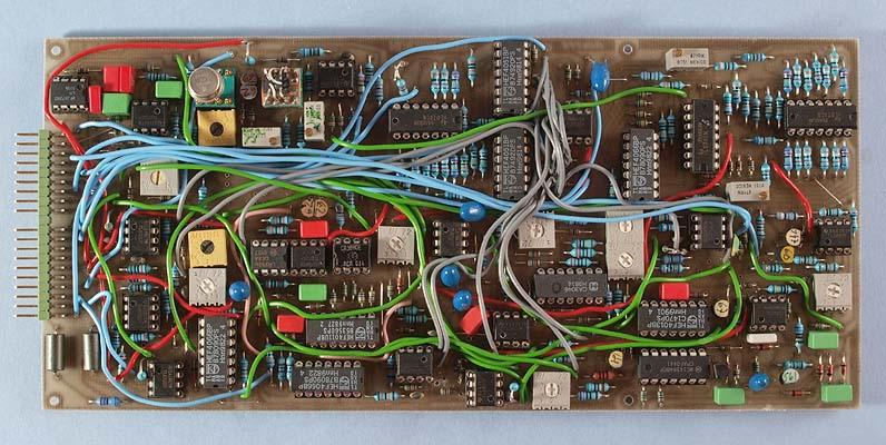
The Advanced VCO is an extended size AMORE board. Even with the extended size board, it was a challenge to fit all circuits on one single board.
With this module I
wanted to include the most important features from my Complex VCO and
in addition my own Woodwind Waveshaper plus Jürgen Haible's
VC-divide by N. The combination of the latter two circuits creates
some unique possibilities, which are detailed below.
With my
concept of ”reusable engineering”, the circuits on this
module are broken down in six separate parts:
Buchla VCO core
Octave quantizer
Advanced VCO waveshaper
Woodwind waveshaper
VC divide by N
Two channel, eight position VC waveform selector
The module generates ten different waveforms. It has two separate outputs and with the waveform selector you can select one of eight combinations of these ten waveforms. Note, however, that the combinations are hard-wired and you can't select waveforms individually for the two outputs. That would have required one more CV input than the AMORE standard allows for. And there was no room on the board for two independent waveform selectors anyway.
The woodwind waveshaper
The advanced VCO
contains a waveshaper circuit of my own design that is mainly
intended to mimic the behaviour of woodwind instruments. It is
inspired by the vintage German wind synth Variophon.
You can read all about the theory on the Variophon
homepage.
According to the theory, the proper way to emulate a
reed instrument is with triangular pulses where you can adjust the up
and down slopes. For some reason, the Variophon used rectangular
pulses instead. Probably because it was easier to implement in
electronics. Because of this, I just had to test it the proper way,
with triangular pulses. And in my circuit the pulse widths are even
voltage controlled. To be able to emulate the Variophon, I added
rectangular pulse too. And as an added bonus I even added a double
pulse, where you can voltage control the width of the positive and
negative pulses separately.
The circuit basically works like a
linear VC-AD envelope shaper. You could actually use it as just that.
The pulse width is independent of the oscillator frequency, which is
according to the reed
instrument theory. This is where this circuit differs from
ordinary pulse width modulation. If you set the up slope slower than
the VCO frequency, the circuit will perform frequency division. This
can be heard in the last sound clip. You can listen to the module in
the following sound clips.
Triangle pulse Double pulse Single pulse Double pulse LFO modulation Double pulse+VCF resonance Sweeping up-PW
The voltage controlled frequency divider
The advanced VCO also
contains a circuit that can divide the frequency in any even number
between 1 and circa 70. The circuit is designed by Jürgen Haible
and he call it the Voltage
Controlled Divide by N. I added an exponential converter to make
the voltage control exponential. This makes it easier to control the
lower division ratios, which are the ones you use most. It also
eliminates the original circuit's annoying habit of cutting out the
signal when the CV goes negative.
Like most, this frequency
divider outputs a square wave. This makes the sound less interesting.
But on the Advanced VCO, the woodwind waveshaper is connected after
the divider. So you get all the different waveforms from the woodwind
waveshaper and frequency division too. And this can be mixed with any
of the other (undivided) waveforms on the module.
Temperature stability
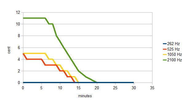
This
swing-in graph was measured by letting the VCO warm up for at least 1
hour, tuning it carefully, switching it off for at least an hour,
turning it back on and immediately start to measure the tuning
(without re-tuning it). This procedure was repeated with the VCO
tuned in four different octaves. As you can see, at lower frequencies
it starts spot on and remains there as long as you pay the
electricity bill. At higher frequencies it goes very slightly sharp
for a couple of minutes while the components warm up. This deviation
is however very minor and already after 10 minutes, it is almost
perfectly in tune.
The waveforms
The Advanced VCO has no
less than ten different waveforms. Four of these have voltage
controlled parameters for modulating the wave-shape and four of them
are affected by the voltage controlled frequency divider, so the
range of waveforms the module can produce is vast.
In addition to
that, you have two waveforms available at a time, which can be mixed
or further processed with the help of additional modules. By the way,
the waveform selection can be voltage controlled too. You could for
instance control it from a sequencer, to have different waveforms for
different notes.
Sine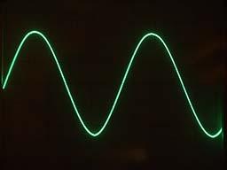
This is an ordinary sine wave. It uses my tried and trusted triangle to sine wave converter, that was inspired by the one in the Moog 921B. Because it is fed by a purer triangle wave, the sine is cleaner than on sawtooth core VCOs.
Triangle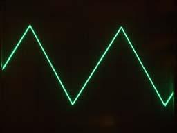
The triangle is the basic waveform that is produced by the VCO core.
Sawtooth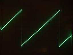
With the triangle and square wave from the core, a 4066, an op-amp and some resistors form a nice sawtooth wave.
Even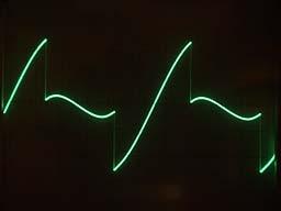
The even harmonic waveform is a sawtooth with double frequency, mixed with a sine wave in the proportions 1:1,27. This creates a waveform that has all the even partials but no odd partials.
Odd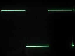
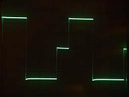
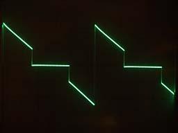
The odd harmonic waveform is simply a square wave. This is the output from the VC divide by N. This means that you can alter the frequency dynamically, by voltage controlling the division ratio. Note that this does not affect several of the other waveforms so you can mix waves with different pitch from the same VCO. There is always an integer ratio between the frequency of these waveform, in contrast to when you mix the output from two different VCOs.
Woodwind
triangle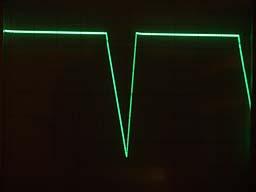
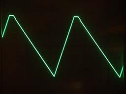
The woodwind waveshaper
generates a triangle wave where you can adjust (and voltage control)
the up- and down-slopes of the triangle wave separately. These slopes
are not proportional to the oscillator frequency, so when you change
the pitch, there will be a different length of gap between each
triangle. This mimics how acoustic woodwind instruments work and
means that there will be fixed formants in the overtone spectrum. If
you modulate the up and down slopes, these formants will move though.
If you want the pulse width to stay proportional to the oscillator
frequency, you can modulate the pulse width with the 1 oct/V note CV
from your keyboard or midi to CV converter. The pulse width will then
track the oscillator frequency, because the pulse width response is
exponential – increasing the pulse width CV one volt cuts the
pulse width in half. If you set the pulse width longer than one
oscillator cycle, frequency division will occur.
This waveform is
also affected by the voltage controlled frequency divider. But in
contrast to most other frequency dividers, which only can output
square waves, the triangle wave-shape remains even after division.
Note that when the frequency is divided, the pulse width still stays
the same. Also note that when you sweep the division ratio, the
triangles will not be cut up, but the start of the next cycle will be
altered. This avoids annoying switching noise.
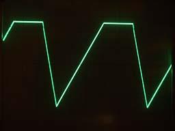
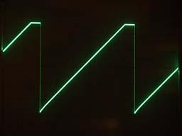
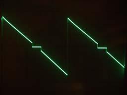
Double pulse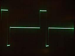
This waveform is generated by the Woodwind waveshaper circuit, so the pulse widths are not proportional to the oscillator frequency. You can modulate the pulse width of the positive and negative parts individually. This waveform is affected by the frequency divider. Note that when the frequency is divided, the pulse width still stays the same.
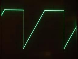
Pulse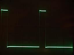
This waveform is also generated by the Woodwind waveshaper circuit, so the pulse width is not proportional to the oscillator frequency. The pulse is similar to what the vintage German wind synth Variophon used. This waveform is affected by the frequency divider. Note that when the frequency is divided, the pulse width still stays the same.
Cut saw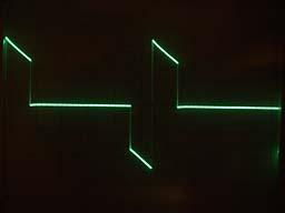
This waveform is a spin-off effect of the fact that I had one unused 4066-section. With it, three op-amps and a couple of resistors, I generate this wave, that is a sawtooth which have had a variable (voltage controlled) portion in the middle cut out. This is similar to ordinary pulse width modulation, but with narrow pulse width the fundamental of this wave is weaker than the lower harmonics. This is never the case with classic pulse width modulation, where the fundamental is always the strongest, even though the lower harmonics are almost as strong at narrow pulse widths. The shape of this waveform is controlled by the same CV input as the down pulse width of the woodwind waveshaper.
Double frequency
saw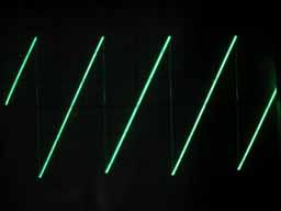
This is a normal sawtooth that has twice the frequency of the other waveforms. It can be useful when mixing with another waveform. It is really a spin-off, as I originally needed it for the odd harmonic waveform (see above). It is generated from basically the same circuit as the ordinary sawtooth. But with different biasing, it produces two "sawteeth" for each period of the triangle wave.
The waveform selector have the following positions:
wave A
wave B
1:
sine
double pulse
2: triangle
pulse
3: sawtooth
woodwind triangle
4: even
odd
5: cut saw
double frequency saw
6: pulse
cut saw
7: double pulse saw
8: woodwind tri
sine
The waveforms are output on the two separate outputs. If you want to cross-fade between the two oscillators, you can connect the outputs to the inputs of the Voltage Controlled Crossfader.
Bill of materials
You should have access
to the parts in the general bill of
materials.
In addition, you need the following less common
parts:
LM311
Comparator (1)
MAT03 Dual PNP transistor recommended for the VCO
core (1)
1 kohm 3500 ppm/°C temperature compensation resistor
(1)
Matching
In the VCO core, the
two 5.1 kiloohm resistors between the emitters of the PNP transistor
pair and the positive supply must be very carefully matched. Buy a
belt of 100 resistors and find two that give the exact same reading
on a 4 1/2 digit ohmmeter. Any error here will give a non-symmetrical
triangle wave. The same effect will be evident if the PNP transistor
pair is not matched well enough. You can adjust small errors with the
20k trimmer.
If the trimmer doesn't have enough range to get a
perfect triangle on the oscilloscope, either the resistors or
the transistor pair must be replaced with something better matched.
You can try to swap the resistors over. This will either make the
error worse or better. If you are lucky, the matching error in the
resistors will cancel that of the transistor pair.
For the PNP
transistor pair, a MAT03 is excellent, but unfortunately very
expensive. Hand-matching two plain-vanilla BC560 can sometimes work
almost as well but it's not quite clear what parameter they should be
matched for. Matching for Vbe doesn't seem to work very well. It's
probably better to match for Hfe. Also, both transistors need to be
kept at exactly the same temperature, otherwise the triangle symmetry
will be affected at low frequencies. My recommendation is to go for
the MAT03 after all.
In the octave quantizer there are five 20k
resistors and three 100k resistors that need to be matched. Use the
same procedure as above. Here the requirements for matching aren't
quite as high as for the VCO core. The matching is done to guarantee
that the octave steps are exactly in tune.
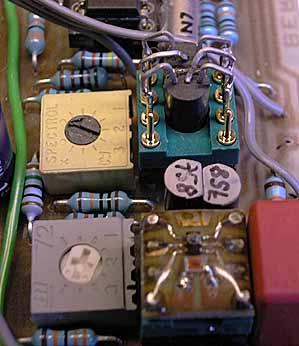
Here we see the tempco/dual NPN module (bottom right) and the PNP module with two matched BC560C (top right). In-between, there are two BC550C, which are matched also. I'm not sure that is necessary though (but it doesn't hurt either..).
Trimming
These are the alignment steps for the Advanced VCO:
1. Adjust the supply voltages to exactly 15.0 volts (on your power supply).
2. Adjust "LF lin" to get as symmetric a triangle wave as possible over the most used frequency range.
3. Adjust the trimmer "saw shape", to get a nice and smooth sawtooth, without any step in the middle. Then adjust "CS offset" and "2F offset" to get the right waveforms, between 0 and +5 V.
4. Adjust "sine sym" and "sine shape" while listening to the sine output. You will hear when you have adjusted them for the cleanest sine wave.
5. Adjust "divide offset" so that the frequency divider outputs the same frequency as the input signal at 0 volt CV.
6. Adjust "slope offset" to get a suitable range for the pulse-width.
7. Adjust "slope track" so that the pulse width halves when the CV is increased 1 volt.
8. Adjust "oct/V" so that the VCO frequency doubles when the CV is increased 1 volt.
9. Adjust "freq offset" to get the desired frequency at o volt CV.
10. Adjust "octaves trim" so that every other step of the octave quantizer doubles the VCO frequency.
11. Adjust "fifths trim" so that the steps in-between increase the frequency exactly a fifth.
Skill level required: HIGH
This board contains a
lot of parts and it requires that some components are carefully
matched. You should not attempt it, if you don't have access to an
oscilloscope and a 4 1/2 digit DMM.
However, the circuits are
divided into several function blocks that can be tested separately.
Each of these blocks aren't overly complicated. So with a bit of
patience, this module shouldn't be outrageously difficult to build.
Schematics
Voltage controlled divide by N
Circuit board layouts
In addition to the
board layout and the component placement plan, there are three
different plans for the on-board wiring. The board contains several
sub-modules that need to be connected with these wires. In addition,
the wave-shapers for the different waveforms have been spread out
over different places due to lack of continuous space on the board.
Finally, there are several wires needed to distribute the supply
voltages to all circuits on the board. The wiring plans contain most
of these. Some are probably missing but it should be easier to figure
the missing ones out when you have soldered the documented ones.
In
addition to this, the chosen waveforms must be connected to the VC
waveform selector. This is not included in the wiring plans as you
decide in which combinations the waveforms are used.
Circuit board layout (PDF-file)
Component placement (PDF-file)
Pink wires (PDF-file)
Blue wires (PDF-file)
Green wires (PDF-file)
|
Connector pin |
signal |
on this module |
|
1 |
1 oct/V |
KOV |
|
2 |
in 1 |
sync |
|
3 |
CV 1 |
octaves CV |
|
4 |
CV 2 |
FM |
|
5 |
CV 3 |
divide CV |
|
6 |
-15 V |
-15 V |
|
7 |
out 1 |
output A |
|
8 |
-1 V |
-1 V |
|
9 |
gnd |
gnd |
|
10 |
key |
- |
|
11 |
switch 1 |
mute A |
|
12 |
switch 2 |
mute B |
|
13 |
out 2 |
output B |
|
14 |
+15 V |
+15 V |
|
15 |
+10 V |
not used |
|
16 |
aux output |
not used |
|
17 |
in 2 |
lin FM |
|
18 |
CV 4 |
PW up CV |
|
19 |
CV 5 |
PW down CV |
|
20 |
CV 6 |
waveform CV |