
Minimoog style VCO
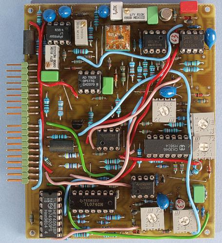
The Minimoog style VCO is just a half size AMORE board. This picture shows a prototype.
This voltage
controlled oscillator has a core that is similar to the one used in
later Minimoogs. But with today's op-amps and some other changes, it
offers even better stability. The exponential converter uses a
conventional NPN transistor pair and a tempco resistor that are
potted together for best temperature stability. This results in
stable tuning with low drift, fast swing-in after switch-on and good
temperature stability. The triangle and sine waveshaper is the same
circuit as used on my earlier VCOs and based on the circuits in the
Moog 921B module.
This VCO has a LFO mode, just like the Basic
VCO. So like on the Minimoog, you can use one or two of the VCOs
as LFO for modulation. In contrast to the Basic
VCO, this module does not switch the timing capacitor but only
adds a negative CV. This avoids some problems with the triangle and
sine waveforms but limits the lowest frequency to circa 0.17 Hz (six
seconds per cycle).
The VCO core and waveform selector areas on
this circuit board are identical to the Woodwind
VCO board.
Note that this board is plug compatible with all
the other AMORE VCO
boards. Differences in the feature sets between boards only mean that
controls for unavailable features do nothing.
The Bergfotron Minimoog style VCO has the following functions:
Sawtooth, pulse, triangle and sine wave
Sync
Linear FM
Voltage controlled waveform selector
Digitally controlled LFO mode
Digitally controlled mute function
Temperature stability
For additional temperature compensation the VCO uses a 1 kohm temperature compensation resistor. The ideal temperature coefficient for this resistor is supposed to be 3300 ppm. I used one with 3000 ppm temperature coefficient. This VCO uses the Bergfotron standard socket for the exponential converter transistor pair and temperature compensation resistor. Here you plug in a component carrier where you solder the transistor pair and tempco resistor of your choice. These should be in thermal contact and preferably potted together for lowest temperature drift. I used surface mount parts (dual transistor + tempco resistor) soldered to a small circuit board on the component carrier which plugs into the 8 pin IC socket. The parts were potted with Araldite. If you don't use surface mount parts, you can solder the dual transistor and tempco resistor directly on the circuit board. For practical reasons I recommend the solution with the component carrier even for these though.
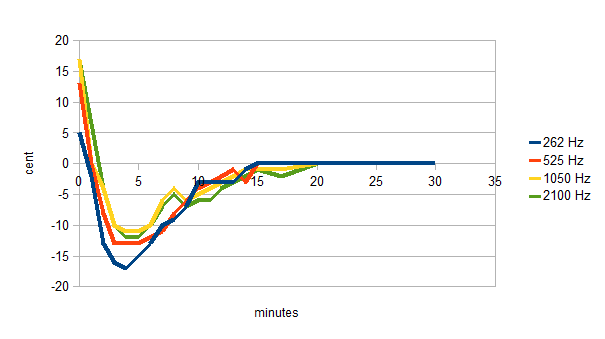
This
swing-in graph was measured by letting the VCO warm up for at least 1
hour, tuning it carefully, switching the power off for at least an
hour, turning it back on and immediately start to measure the tuning
(without re-tuning it). This procedure was repeated with the VCO
tuned in four different octaves. As you can see, it starts very
slightly sharp but immediately goes slightly flat for a couple of
minutes while the components warm up. This deviation is however very
minor, and already after 10 minutes it is almost in tune. After
warm-up there is essentially no drift. However, I have not been able
to measure the stability over varying ambient temperatures yet.
These
measurements were made with the AMORE Starter Kit and also include
the warm-up and temperature stability of the AMORE power supply
(which is very good).
You might have expected that the swing-in
behaviour would be exactly the same as on the Woodwind
VCO, since it uses the same VCO core. Well, I suppose the slight
difference is due to component variations.
The waveforms
This module produces the four classic synth waveforms. Measured on the oscilloscope at 1 kHz.
Sawtooth
Sine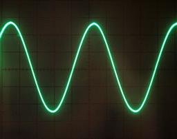
Triangle
Pulse
Bill of materials
You should have access
to the parts in the general bill of
materials.
In addition, you need the following less common
parts:
8
pin DIL component carrier
1 kohm 3500 ppm/°C temperature
compensation resistor (1)
Dual NPN transistor or a hand-matched
transistor pair (1). The 2SC1583 is a good choice, if you can find
it. I have used a SMD type transistor pair and SMD type tempco
resistor mounted on a small circuit board on a 8 pin component
carrier. Even if you use conventional parts, it is a good idea to
mount them on a component carrier and cover them with heat insulating
material. I used epoxy glue for this.
2N4391 or compatible FET.
This must be a fast switching, low Rds-on type.
LF412 dual OP-amp
(1). Other decently fast op-amps with low offset and drift can be
used.
OP177 single precision op-amp (1). Other ultra-low drift
op-amps can be used. This one doesn't have to be fast.
Matching
No hand-matching required if you use a matched transistor pair.
Trimming
These are the alignment steps for the Minimoog style VCO core:
1. Adjust the supply voltages to exactly 15.0 and 10.0 volts (on your power supply). Note that this module uses the 10 V supply for the tuning-critical parts, so his has to be very stable. Using the AMORE power supply is recommended.
2. Adjust "scale" to get exactly 1 octave per volt on the KOV input.
3. Adjust the HF-trimpot to get exactly 1 octave per volt at higher frequencies (above 2 kHz).
4. Adjust "init freq." to the desired base frequency so the VCO is in tune with other VCOs when fed the same control voltage.
Alignment of the triangle and sine converters:
1. Set the VCO to around 500 – 1000 Hz and adjust “tri offset” so that the triangle wave is roughly centred on the oscilloscope (relative to 0 volts).
2. Adjust “tri shape to make a good triangle shape. This will change the DC offset, so repeat steps 1 and 2 until you are satisfied.
3. Connect an amp/loudspeaker to the VCO and switch to the sine waveform.
4. Adjust “sine offset” so that the sine wave is roughly centred on the oscilloscope.
5. Adjust “sine sym” to give a symmetric waveform on the oscilloscope
6. Adjust sine shape while listening to the sound. You will hear when there is a minimum of overtones.
7. Redo step 5 and 6 while listening to the sound. You will hear when you have the purest possible sine.
8. Recheck the DC offset and adjust if necessary.
Skill level required: MEDIUM
This board is quite densely populated but does not require matching of components. For best temperature tracking you should glue the tempco resistor and the exponential converter transistors together.
Triangle and sine converter schematics
Voltage controlled waveform selector schematics
The component placement
plan contains pairs of capital letters. These are supposed to be
connected with insulated wires.
|
Connector pin |
signal |
on this module |
|
1 |
1 oct/V |
KOV |
|
2 |
in 1 |
sync |
|
3 |
CV 1 |
not used |
|
4 |
CV 2 |
frequency CV |
|
5 |
CV 3 |
not used |
|
6 |
-15 V |
-15 V |
|
7 |
out 1 |
main output |
|
8 |
-1 V |
-1 V |
|
9 |
gnd |
gnd |
|
10 |
key |
- |
|
11 |
switch 1 |
mute main output |
|
12 |
switch 2 |
audio / LFO |
|
13 |
out 2 |
sawtooth output |
|
14 |
+15 V |
+15 V |
|
15 |
+10 V |
+10 V |
|
16 |
aux output |
sine output |
|
17 |
in 2 |
lin FM |
|
18 |
CV 4 |
pulse width CV |
|
19 |
CV 5 |
not used |
|
20 |
CV 6 |
waveform CV |