
Woodwind VCO
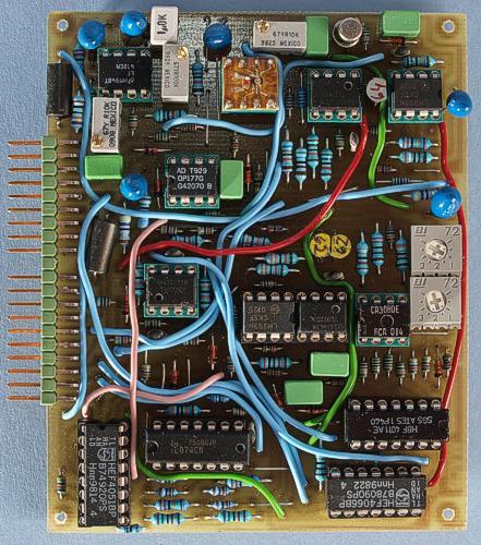
The Woodwind VCO is amazingly just a half size AMORE board. This picture shows a prototype.
I call this the
Woodwind VCO because it is loosely based on woodwind instrument
theory (see below). This doesn't mean it only can produce
woodwind-like sounds though. The VCO is based on a Minimoog style
sawtooth core. This feeds the woodwind waveshaper of my own design
(see below), which produces three different waveforms. In addition,
you have the sawtooth wave from the core for those warm and fat synth
brass sounds. All four waveforms are selectable under voltage control
and available on output 1. The sawtooth also has a separate output –
it is always available on output 2. Amazingly, I was able to fit all
this circuitry on a half size AMORE board. That of course means the
circuit board is quite densely packed.
This VCO has surprisingly
stable tuning with low drift, fast swing-in after switch-on and good
temperature stability. The voltage controlled oscillator core is
similar to the one used in later Minimoogs but utilizes today's
op-amps for even better stability. The exponential converter uses a
conventional NPN transistor pair and a tempco resistor that are
potted together for best temperature stability. The woodwind
waveshaper is the same circuit as used on the Advanced
VCO but here you will not get all the other waveforms, no voltage
controlled divider and no octave selector.
The Bergfotron Woodwind VCO has the following functions:
Sawtooth wave plus three special waves (see text)
Sync
Linear FM
Voltage controlled waveform selector
Digitally controlled mute function
Compared to other VCO modules, the Woodwind VCO does NOT offer:
Sine wave
Conventional triangle wave
LFO mode
Octave selector
The woodwind waveshaper
The Woodwind VCO
contains a waveshaper circuit of my own design that is mainly
intended to mimic the behaviour of woodwind instruments. It is
inspired by the vintage German wind synth Variophon.
You can read all about the theory on the Variophon
homepage.
According to the theory, the proper way to emulate a
reed instrument is with triangular pulses where you can adjust the up
and down slopes. For some reason, the Variophon used rectangular
pulses instead. Probably because it was easier to implement in
electronics back in the 70's. Because of this, I just had to test it
the proper way, with triangular pulses. And in my circuit the pulse
widths are even voltage controlled. To be able to emulate the
Variophon, I added rectangular pulse too. And as an added bonus I
even added a double pulse, where you can voltage control the width of
the positive and negative pulses separately.
The circuit
basically works like a linear VC-AD envelope shaper. You could
actually use it as just that (see my Dual
VCAD module). Note that the pulse width is independent of the
oscillator frequency, which is according to the
reed instrument theory. This is where this circuit differs from
ordinary pulse width modulation. If you set the up slope slower than
the VCO frequency, the circuit will perform frequency division. This
can be utilized to good effect when emulating wind instrument
attacks. You can hear it in the last of the following sound clips.
Woodwind triangle Double pulse Single pulse Double pulse LFO modulation Double pulse+VCF resonance Sweeping PW up
Temperature stability
For additional temperature compensation the VCO uses a 1 kohm temperature compensation resistor. The ideal temperature coefficient for this resistor is supposed to be 3300 ppm. I used one with 3000 ppm temperature coefficient. This VCO uses the Bergfotron standard socket for the exponential converter transistor pair and temperature compensation resistor. Here you plug in a component carrier where you solder the transistor pair and tempco resistor of your choice. These should be in thermal contact and preferably potted together for lowest temperature drift. I used surface mount parts (dual transistor + tempco resistor) soldered to a small circuit board on the component carrier which plugs into the 8 pin IC socket. The parts were potted with Araldite. If you don't use surface mount parts, you can solder the dual transistor and tempco resistor directly on the circuit board. For practical reasons I recommend the solution with the component carrier even for these though.
This
swing-in graph was measured by letting the VCO warm up for at least 1
hour, tuning it carefully, switching the power off for at least an
hour, turning it back on and immediately start to measure the tuning
(without re-tuning it). This procedure was repeated with the VCO
tuned in four different octaves. As you can see, it starts almost
spot on but goes slightly flat for a couple of minutes while the
components warm up. This deviation is however very minor, especially
at higher frequencies, and already after 10 minutes it is almost
perfectly in tune. After warm-up there is essentially no drift.
However, I have not been able to measure the stability over varying
ambient temperatures yet.
These measurements were made with the
AMORE Starter Kit and also include the warm-up and temperature
stability of the AMORE power supply (which is very good).
The waveforms
Sawtooth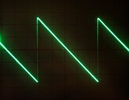
The sawtooth is the basic waveform that is produced by the VCO core. Measured on the oscilloscope at 1 kHz.
Woodwind
triangle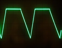
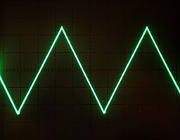
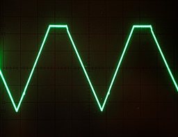
A few of the different waveforms possible by adjusting the PW up and PW down knobs. As you can see, it can produce a normal triangle wave. But note that the waveform is frequency dependent unless you add the note CV to the PW up and PW down CVs.
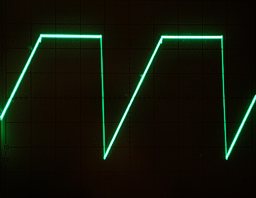
Pulse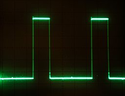
The pulse has a traditional shape but the pulse width has a fixed time, independent of VCO frequency.
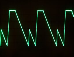
Double
pulse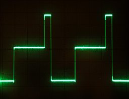
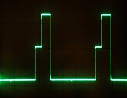
The double pulse wave can produce different shapes, depending on the PW up and PW down CVs.
Bill of materials
You should have access
to the parts in the general bill of
materials.
In addition, you need the following less common
parts:
8
pin DIL component carrier
1 kohm 3500 ppm/°C temperature
compensation resistor (1)
Dual NPN transistor or a hand-matched
transistor pair (1). The 2SC1583 is a good choice, if you can find
it. I have used a SMD type transistor pair and SMD type tempco
resistor mounted on a small circuit board on a 8 pin component
carrier. Even if you use conventional parts, it is a good idea to
mount them on a component carrier and cover them with heat insulating
material. I used epoxy glue for this.
2N4391 or compatible FET.
This must be a fast switching, low Rds-on type.
LF412 dual OP-amp
(1). Other decently fast op-amps with low offset and drift can be
used.
OP177 single precision op-amp (1). Other ultra-low drift
op-amps can be used. This one doesn't have to be fast.
Matching
No hand-matching required if you use a matched transistor pair. You can match the PNP transistors for the expo converter in the woodwind waveshaper if you want. This isn't very important though.
Trimming
These are the alignment steps for the Woodwind VCO:
1. Adjust the supply voltages to exactly 15.0 and 10.0 volts (on your power supply). Note that this module uses the 10 V supply for the tuning-critical parts, so his has to be very stable. Using the AMORE power supply is recommended.
2. Adjust "scale" to get exactly 1 octave per volt on the KOV input.
3. Adjust the HF-trimpot to get exactly 1 octave per volt at higher frequencies (above 2 kHz).
4. Adjust "init freq." to the desired base frequency so the VCO is in tune with other VCOs when fed the same control voltage.
5. Set the PW up and PW down pots fully clockwise (shortest pulse width) and adjust the Offset trimmer so that the pulse width just reach the shortest possible.
6. Adjust the tracking trimpot so that each one volt increase of the pulse width CVs exactly halves the pulse width.
Skill level required: MEDIUM
This board is quite densely populated but does not require matching of components. For best temperature tracking you should glue the tempco resistor and the exponential converter transistors together.
Woodwind waveshaper schematics
Voltage controlled waveform selector schematics
The component placement
plan contains pairs of capital letters. These are supposed to be
connected with insulated wires.
|
Connector pin |
signal |
on this module |
|
1 |
1 oct/V |
KOV |
|
2 |
in 1 |
sync |
|
3 |
CV 1 |
not used |
|
4 |
CV 2 |
FM |
|
5 |
CV 3 |
not used |
|
6 |
-15 V |
-15 V |
|
7 |
out 1 |
main output |
|
8 |
-1 V |
-1 V |
|
9 |
gnd |
gnd |
|
10 |
key |
- |
|
11 |
switch 1 |
mute main output |
|
12 |
switch 2 |
not used |
|
13 |
out 2 |
sawtooth output |
|
14 |
+15 V |
+15 V |
|
15 |
+10 V |
+10 V |
|
16 |
aux output |
not used |
|
17 |
in 2 |
lin FM |
|
18 |
CV 4 |
PW up CV |
|
19 |
CV 5 |
PW down CV |
|
20 |
CV 6 |
waveform CV |