
Analog Modules Of Reusable Engineering (AMORE)
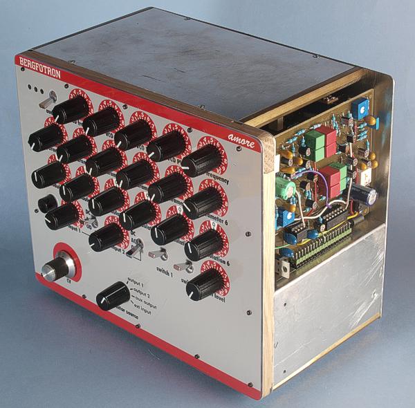
This is the AMORE Starter Kit with the Minikorg VCF board in operation.
I have realized that some of my earlier modules (the Complex VCO comes to mind) have been too complicated for most hobbyists. And even for myself, these multi-board modules are difficult to maintain and troubleshoot. They are also somewhat failure-prone, as internal wiring cables can break at their solder joints. These are just a few reasons why I have come up with a brand new concept for building synth circuits. I call my new concept Analog Modules Of Reusable Engineering (AMORE). Further advantages of the system:
AMORE boards can be tested independently of the front panels/wiring and the rest of the synth. Makes it a lot easier to find the problem in case of malfunctions in a completed synth.
AMORE boards are gangable for building a polyphonic synth.
AMORE boards can be controlled from a preset system.
AMORE boards can be computer-controlled (for patch programming etc.).
AMORE boards can be built, tested and calibrated separately, without a synth to host them (the AMORE exerciser is used instead of the synth). This way, you don’t have to do a lot of boring metalwork before you can try out your new circuit.
AMORE boards can be kept as spares and quickly swapped, for fast synth repair.
You can change functionality in a completed synth (filter type etc.) by replacing an AMORE board with another type.
You could upgrade the performance (temperature stability etc.) of your synth by switching to a higher specified AMORE board.
AMORE boards are reusable. You could build a larger synth and just plug in the boards from your old synth into the new.
AMORE is a reasonably well defined standard. Other hobbyists/manufacturers could produce different AMORE boards that would be plug-compatible with your synth.
The AMORE standard consists mainly of two parts: The physical dimensions of the board and the connector with its electrical specifications. The standard does not define any front panel. You can make the AMORE based modules compatible with the earlier Bergfotron modules or with most of the commercial modular synths by mating the board to a front panel that corresponds to the standards of your chosen synth manufacturer.
The board dimensions are based on the standard 100 x 160 mm circuit board. There are three different board sizes: Half, Full and Extended. The half board is simply a 100 x 160 mm board cut in half. So the size is 100 x 80 mm. The full board is 100 x 160 and the extended board is 100 x 220 mm. The boards have four 2 mm mounting holes with 5 mm clearance. For half sized boards the hole distance is 74 x 94 mm, centered on the board. For full sized boards the hole distance is 154 x 94 mm, centered. The extended boards have the same hole pattern as the full sized board and the hole placement is the same, with respect to the connector end.
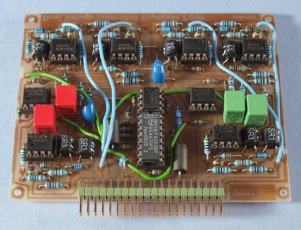
This is what an AMORE board looks like
The AMORE standard connector
All AMORE boards use a standard connector with a standardized set of signals. Of course modules might use a subset of these signals. The electrical connector is a 2 x 20 pin type where the two rows of pins are connected in parallel, for increased reliability. You could use a single row of 20 pins if you want to economize. There are no other connections to the board than this standard connector. This means that you can very easily take a board out of the synth and replace it with another – even one with different/updated circuitry.
Because of the fixed set of connector pins, the boards have a fixed maximal number of inputs and outputs. There are two inputs and three outputs for signals. In addition there are six inputs for control voltages and one input for 1 oct/volt pitch control voltage. Of course, any module could use a subset of this. In fact, there is no difference in the electrical specification for the signal- and control voltage inputs. So if you need more than two signal inputs, some of the control voltage inputs could be used for signals instead.
All signal- and control voltage inputs are summing nodes, so you can mix any number of signal sources into each input. This also means that an external resistor is required for each input, to connect a signal source. For control voltages there will normally be one resistor that connects to the front panel parameter potentiometer and another one (or several) that connect modulation sources. All these resistors should be 100 kohm if you follow the recommended standard with 0 – 10 V control voltages and +-5 V p-p signals. The 1 oct/V keyboard input and the switch inputs are exceptions to this rule. They should be fed the signals directly. The switch inputs use 0 volts for ”off” and 15 volts for ”on”.
So any module can have no more than two inputs, two outputs and six controllable parameters (but see above). My research has proved this to be enough. Of course you could think of specialty modules that require more. You simply have to make non-standard boards for those. For simple circuits, an AMORE board can contain dual modules with one input, one output and three parameters per circuit.
In the electrical specification, there is also two switch inputs. They are often used for a mute/bypass feature. This is added to make it easy to hear what effect a module has to the final sound. The more modules your patch involves, the more important this feature gets. This feature can also be handy if you use the module in a guitar stompbox. On some modules one of these inputs control some specific feature in the circuit.
From the specifications it is obvious that a module cannot have functions that are controlled directly by a pot or switch. All functions must be voltage controlled, even switch type functions like selecting waveforms or filter modes.
|
Connector pin |
signal |
|
1 |
1 oct/V |
|
2 |
in 1 |
|
3 |
CV 1 |
|
4 |
CV 2 |
|
5 |
CV 3 |
|
6 |
-15 V |
|
7 |
out 1 |
|
8 |
-1 V |
|
9 |
gnd |
|
10 |
key |
|
11 |
switch 1 |
|
12 |
switch 2 |
|
13 |
out 2 |
|
14 |
+15 V |
|
15 |
+10 V |
|
16 |
aux output |
|
17 |
in 2 |
|
18 |
CV 4 |
|
19 |
CV 5 |
|
20 |
CV 6 |
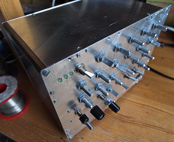
The AMORE Starter Kit awaiting front panel with lettering.
To get started with AMORE modules you should first build the AMORE Starter Kit. This is a set of three circuit boards that you can mount in a small box with all the knobs, inputs and outputs for a single module. It even contains a regulated power supply – you just add mains transformers. A simpler unit with the functions for controlling the module's functions but no power supply or signal generator is called the AMORE Exerciser. You can add the Exerciser as an expansion, if you want to run two modules at a time.
You use the Starter Kit for testing and troubleshooting your new boards. It has all controls for all the functions that the AMORE standard allows. Each AMORE module uses a subset of these. As the Starter Kit is already tested, you can rule out errors in the pot wiring, and such, when your module isn’t working. This simplifies the process of getting the boards functional. You also use the Starter Kit for trimming/calibrating the boards. When all modules are built, you use the Starter Kit for calibrating/servicing existing modules. It’s much easier to take a board out and put it in the Stater Kit for service than to put the entire synth on the workbench.
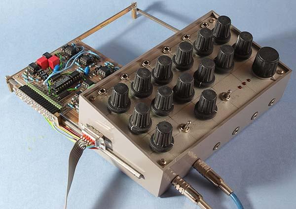
The
AMORE Exerciser in use.
Not having to make a front panel before being able to test a new board makes it a lot easier and more fun to try out new circuit ideas. If the circuit didn’t work out, you haven’t wasted time and materials on a panel that you have no use for. Usually the cost for the panel (with pots, knobs, switches and jacks) is far higher than for the circuit board and its components. So with AMORE you could potentially save some cash too.
The AMORE standard is
open for other hobbyists/manufacturers to make compatible boards.
Feel free to contact me if you have suggestions for
changes/enhancements to the standard.
There are already ten
different AMORE modules and I'm planning on replacing most of my old
modules with AMORE versions. Additionally, there will be further,
completely new modules.
General instructions for building AMORE boards
Circuit diagram for the AMORE exerciser
Available AMORE boards
Dual voltage controlled bandpass filter
Dual log VCA with noise generator
Voltage controlled ADSHR envelope generator
Dual voltage controlled AD envelope generator
AMORE FAQ
Q: Why only two inputs? I need more inputs!
A: To begin with, each input is a summing node. So you can mix any number of signals into the two inputs. If you still need more inputs, you can use some of the CV inputs for signal inputs instead. The exerciser handles this situation. Just set the CV knob to 0, connect the signals to the modulation inputs and use the modulation amount knobs to set the signal level. However, AMORE is not intended for things like vocoders, sequencers or graphic equalizers.
Q: Why no digital inputs?
A: The two switch inputs are digital inputs. And remember, digital is just a special case of analog. You can additionally use some of the CV inputs for your digital control signals. If the module doesn't process audio signals, you use the signal inputs for inputting digital signals. Example: the gate signal for an envelope generator or a sync signal for an LFO.
Q: Why no CV outputs?
A: If your module generate control signals, you use one or more of the three signal outputs for the generated CVs.
Q: I cant seem to find 2x20 pin header connectors. What to do?
A: Use a longer type and cut it to 20 pin length.